Nissan Juke Service and Repair Manual : Wiring diagram
4WD SYSTEM
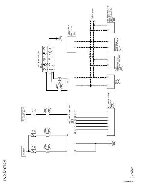
Wiring Diagram
For connector terminal arrangements, harness layouts, and alphabets in a
 (option abbreviation; if not
described in wiring diagram), refer to GI-12, "Connector Information/Explanation
of Option Abbreviation".
 ECU diagnosis information
4WD control module
Reference Value
VALUES ON THE DIAGNOSIS TOOL
TERMINAL LAYOUT
PHYSICAL VALUES
*: The values are changed by throttle opening and engine speed.
CAUTION:
When using ...
 Basic inspection
...
Other materials:
P0720 output speed sensor
DTC Logic
DTC DETECTION LOGIC
DTC CONFIRMATION PROCEDURE
CAUTION:
Be careful of the driving speed.
1.PREPARATION BEFORE WORK
If another "DTC CONFIRMATION PROCEDURE" occurs just before, turn ignition
switch OFF and wait for at
least 10 seconds, then perform the next test.
> ...
Outside key antennA
Driver side
DRIVER SIDE : Removal and Installation
REMOVAL
Remove the driver side outside handle. Refer to DLK-339, "OUTSIDE HANDLE :
Removal and Installation".
INSTALLATION
Install in the reverse order of removal.
Passenger side
PASSENGER SIDE : Removal and Installation
REMOVA ...
P2138 APP sensor
DTC Logic
DTC DETECTION LOGIC
NOTE:
If DTC P2138 is displayed with DTC P0643, first perform the trouble diagnosis
for DTC P0643. Refer to
EC-307, "DTC Logic".
DTC CONFIRMATION PROCEDURE
1.PRECONDITIONING
If DTC Confirmation Procedure has been previously conducted, always perform ...
