Nissan Juke Service and Repair Manual : Precaution for Liquid Gasket
REMOVAL OF LIQUID GASKET
ŌĆó After removing the mounting bolts and nuts, separate the mating surface using a seal cutter and remove the liquid gasket.
CAUTION:
Be careful not to damage the mating surfaces.
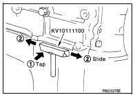
ŌĆó In areas where the cutter is difficult to use, use a plastic hammer to lightly tap the gasket applied area.
CAUTION:
If for some unavoidable reason a tool such as a flat-bladed
screwdriver is used, be careful not to damage the mating surfaces
.
LIQUID GASKET APPLICATION PROCEDURE
1. Using a scraper, remove the old liquid gasket adhering to the gasket application surface and the mating surface.
ŌĆó Remove the liquid gasket completely from the groove of the gasket application surface, mounting bolts and bolt holes.
2. Wipe the gasket application surface and the mating surface with white gasoline (lighting and heating use) to remove adhering moisture, grease and foreign materials.
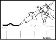
3. Attach the liquid gasket to the tube presser.
Use Genuine Liquid Gasket or equivalent.
4. Apply the gasket without breaks to the specified location with the specified dimensions.
ŌĆó If there is a groove for the liquid gasket application, apply the gasket to the groove.
ŌĆó As for the bolt holes, normally apply the gasket inside the holes. If specified, it should be applied outside the holes. Make sure to read the instruction in this manual.
ŌĆó Within five minutes of gasket application, install the mating component.
ŌĆó If the liquid gasket protrudes, wipe it off immediately.
ŌĆó Do not retighten after the installation.
ŌĆó After 30 minutes or more have passed from the installation, fill the engine oil and coolant.
CAUTION:
If there are instructions in this manual, observe them.
 Precaution Necessary for Steering Wheel Rotation
after Battery Disconnect
Precaution Necessary for Steering Wheel Rotation
after Battery Disconnect
NOTE:
ŌĆó Before removing and installing any control units, first turn the ignition
switch to the LOCK position, then disconnect
both battery cables.
ŌĆó After finishing work, confirm that all co ...
 Preparation
Special Service Tool
...
Other materials:
Continuously Variable Transmission (CVT)
The Continuously Variable Transmission (CVT) in your vehicle is electronically
controlled to produce maximum power and smooth operation.
The recommended operating procedures for this transmission are shown on the following
pages.
Follow these procedures for maximum vehicle performance and driv ...
Steering switch ground circuit
Description
Transmits the steering switch signal to NAVI control unit.
Diagnosis Procedure
1.CHECK STEERING SWITCH SIGNAL GROUND CIRCUIT
1. Disconnect NAVI control unit connector and spiral cable connector.
2. Check continuity between NAVI control unit harness connector and spiral cable
harne ...
Interior room lamp control circuit
Description
Controls each interior room lamp (ground side) by PWM signal.
NOTE:
PWM signal control period is approximately 250 Hz (in the gradual
brightening/dimming).
Component Function Check
CAUTION:
Before performing the diagnosis, check that the following are normal.
ŌĆó Interior room ...
