Nissan Juke Service and Repair Manual : Wheel sensor
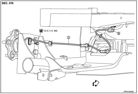
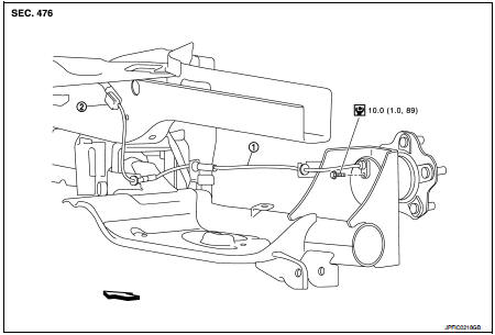
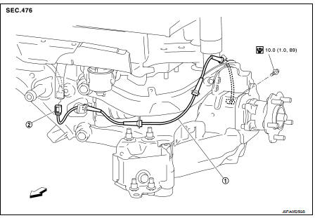
Front wheel sensor : Exploded View
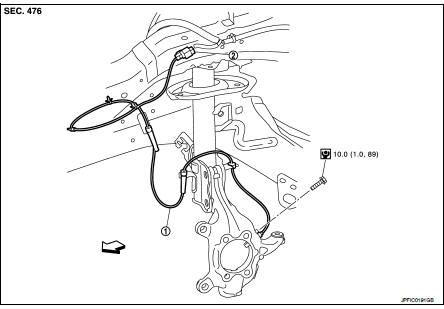
1. Front LH wheel sensor 2. Front LH wheel sensor harness connector
 : Vehicle front
 : N·m (kg-m, in-lb)
NOTE:
Front RH wheel sensor is symmetrically opposite of LH.
Front wheel sensor : Removal and Installation
REMOVAL
1. Remove tires.
2. Remove the fender protector (front). Refer to EXT-22, "Removal and Installation".
3. Remove front wheel sensor from steering knuckle.
CAUTION:
Never rotate and never pull front wheel sensor as much as possible, when pulling
out.
4. Remove front wheel sensor harness from the vehicle.
CAUTION:
Never twist or pull front wheel sensor harness, when removing.
INSTALLATION
Note the following, and install in the reverse order of the removal.
• Check that there is no foreign material like iron powder or damage on inner surface of front wheel sensor mounting hole of steering knuckle and sensor rotor. Install after cleaning when there are foreign material like iron powder, or replace when there is a malfunction.• Check that there is no foreign material like iron powder or damage on inner surface of front wheel sensor mounting hole of steering knuckle and sensor rotor. Install after cleaning when there are foreign material like iron powder, or replace when there is a malfunction.
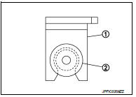
• Never twist front wheel sensor harness when installing front wheel sensor. Check that grommet (2) is fully inserted to bracket (1).
Check that front wheel sensor harness is not twisted after installation.
• Never twist front wheel sensor harness when installing front wheel sensor. Check that grommet (2) is fully inserted to bracket (1).
Check that front wheel sensor harness is not twisted after installation.
Rear wheel sensor : Exploded View
2WD
Left side
1. Rear LH wheel sensor 2. Rear LH wheel sensor harness connector
: Vehicle front
: N·m (kg-m, in-lb)
Right side
1. Rear RH wheel sensor 2. Rear RH wheel sensor harness connector
: Vehicle front
: N·m (kg-m, in-lb)
4WD
1. Rear LH wheel sensor 2. Rear LH wheel sensor harness connector
: Vehicle front
: N·m (kg-m, in-lb)
NOTE
:
Rear RH wheel sensor is symmetrically opposite of LH.
Rear wheel sensor : Removal and Installation
REMOVAL
1. Remove rear wheel sensor from wheel hub and bearing assembly (2WD).
CAUTION:
Never rotate or pull rear wheel sensor as much as possible, when pulling out.
2. Remove rear wheel sensor from axle housing (4WD).
CAUTION:
Never rotate or pull rear wheel sensor as much as possible, when pulling out.
3. Remove rear wheel sensor harness from the vehicle.
CAUTION:
Never twist and never pull rear wheel sensor harness, when removing.
INSTALLATION
Note the following, and install in the reverse order of the removal.
• Check that there is no foreign material like iron powder or damage on inner surface of rear wheel sensor mounting hole of wheel hub and bearing assembly and sensor rotor. Install after cleaning when there are foreign material like iron powder, or replace when there is a malfunction.
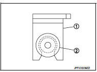
• Never twist rear wheel sensor harness when installing rear wheel sensor. Check that grommet (2) is fully inserted to bracket (1).
Check that rear wheel sensor harness is not twisted after installation.
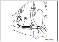
CAUTION:
Check that the identification line (A) of the rear wheel sensor
is faced upward.

 Sensor rotor
Front sensor rotor : Removal and Installatio
REMOVAL
Replace wheel hub as an assembly when replacing because sensor rotor cannot
be disassembled.
• MR16DDT: Refer to FAX-11, "Removal and ...
Other materials:
Drive belt auto tensioner and idler pulley
Exploded View
1. Front cover
2. Drive belt auto-tensioner
: N·m (kg-m, ft-lb)
Removal and Installation
Removal
1. Loosen mounting bolt and remove drive belt auto-tensioner.
Installation
Install in the reverse order of removal.
CAUTION:
When installing drive belt auto-tensioner, be ...
Body maintenance
Locks, hinges and hood latch
LOCKS, HINGES AND HOOD LATCH : Lubr
Seat belt, buckles, retractors, anchors and adjusters
SEAT BELT, BUCKLES, RETRACTORS, ANCHORS AND ADJUSTERS : Inspection
For front seat belt illustration. Refer to SB-4, "Exploded View".
For rear seat belt illustrati ...
Uniform tire quality grading
The Department of Transportation (DOT) mandates Quality Grades for all passenger car tires. All tires must conform to stringent federal safety requirements in addition to these comparative performance grades.
These quality grades are embossed on the tire sidewall, located in the area between th ...
