Nissan Juke Service and Repair Manual : Washer tank
Exploded View
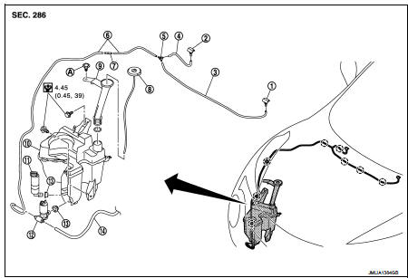
1. Front washer nozzle LH
2. Front washer nozzle RH
3. Front washer tube LH
4. Front washer tube RH
5. Check valve
6. Front washer tube
7. Joint
8. Washer tank inlet cap
9. Washer tank inlet
10. Washer tank
11. Headlamp washer pump
12. Washer pump
13. Packing
14. Rear washer tube
A : Clip
 : Clip
 : N·m (kg·m, in-lb)
Removal and Installation
REMOVAL
1. Fully open hood.
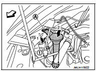
2. Remove washer tank inlet fixing clip (A).
3. Pull out washer tank inlet (1) from washer tank.
 : Vehicle front
4. Remove fender protector RH (front). Refer to EXT-22, "Removal and Installation".
5. Disconnect washer pump connector.
6. Disconnect headlamp washer pump connector.
7. Disconnect washer level switch connector.
8. Disconnect front washer tube and rear washer tube.
9. Disconnect headlamp washer tube joint.
10. Remove washer tank mounting bolts.
INSTALLATION
Note the following item, and then install in the reverse order of removal.
CAUTION:
Add water up to the top of washer tank inlet after installing and check that
there is no leakage.
 Headlamp washer nozzle and tube
Exploded View
1. Washer tank
2. Headlamp washer tube (tank side)
3. Headlamp washer tube RH
4. Headlamp washer nozzle connector
RH
5. Headlamp washer nozzle bracket RH
6. Headlamp washer n ...
 Washer pump
Exploded View
1. Front washer nozzle LH
2. Front washer nozzle RH
3. Front washer tube LH
4. Front washer tube RH
5. Check valve
6. Front washer tube
7. Joint
8. Washer tank inlet cap
...
Other materials:
Cylinder head
Exploded View
REMOVAL
1. Cylinder head assembly
2. Cylinder head bolt
3. Washer
4. Cylinder head gasket
A.Tightening must be done following the installation procedure.
Refer to EM-209
: Always replace after every
disassembly.
: N·m (kg-m, ft-lb)
: Should be lubricated with oil.
...
The ambient temperature display is incorrect
Description
• The displayed ambient air temperature is higher than the actual
temperature.
• The displayed ambient air temperature is lower than the actual temperature.
Diagnosis Procedure
NOTE:
Check that the symptom is not applicable to the normal operating condition
before starting d ...
Security systems
To provide comprehensive protection, your Nissan Leaf is equipped with two distinct security systems designed to safeguard your vehicle:
Vehicle security system
NISSAN Vehicle Immobilizer System
The current operational status of these systems ...
