Nissan Juke Service and Repair Manual : Headlamp washer nozzle and tube
Exploded View
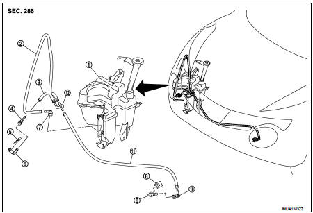
1. Washer tank
2. Headlamp washer tube (tank side)
3. Headlamp washer tube RH
4. Headlamp washer nozzle connector
RH
5. Headlamp washer nozzle bracket RH
6. Headlamp washer nozzle RH
7. Headlamp washer nozzle joint
8. Headlamp washer nozzle bracket LH
9. Headlamp washer nozzle LH
10. Headlamp washer nozzle connector
LH
11. Headlamp washer tube LH 12. Check valve
Hydraulic Layout
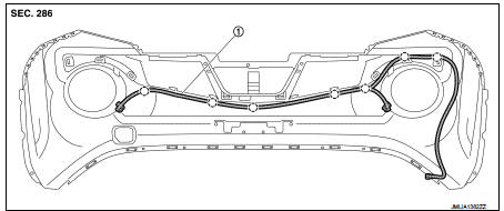
1. Headlamp washer nozzle tube
 : Clip
Removal and Installation
REMOVAL
1. Remove front bumper fascia. Refer to EXT-13, "Removal and Installation".
2. Disengage headlamp washer tube fixing clip from front bumper.
3. Remove headlamp washer nozzle bracket.
4. Remove headlamp washer nozzle from the front bumper fascia.
INSTALLATION
Install in the reverse order of removal.
Inspection
CHECK VALVE INSPECTION
Check that air can pass through the hose by blowing forward (toward the nozzle), and check that air cannot pass through by sucking.

 Washer tank
Exploded View
1. Front washer nozzle LH
2. Front washer nozzle RH
3. Front washer tube LH
4. Front washer tube RH
5. Check valve
6. Front washer tube
7. Joint
8. Washer tank inlet cap
...
Other materials:
Removal and installation
POWER SOCKET
Exploded View
1 : Inner socket
2 : Ring
Removal and Installation
REMOVAL
1. Remove cluster tray. Refer to IP-13, "Removal and Installation".
2. Pull out inner socket (1) by pushing the pawl (B) of the ring (2)
from the inner socket hole (square) (A).
3. Press the ...
Vehicle does not enter 4WD mode
Description
Vehicle does not enter 4-wheel drive mode even though 4WD warning lamp turned
to OFF.
Diagnosis Procedure
1.CHECK 4WD WARNING LAMP
Turn the ignition switch ON.
Does 4WD warning lamp turn ON?
YES >> GO TO 2.
NO >> Proceed to diagnosis procedure. Refer to DLN-80, & ...
Steering Assist limitations
WARNING
In the following situations, the front-facing camera may fail to identify lane markers accurately or misinterpret road features, which may result in the Steering Assist system failing to operate as intended:
When navigating roads with confusing, ...
