Nissan Juke Service and Repair Manual : Diagnosis and repair workflow
Work Flow
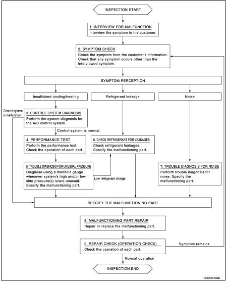
OVERALL SEQUENCE
DETAILED FLOW
1.INTERVIEW FOR MALFUNCTION
Interview the symptom to the customer
>> GO TO 2.
2.SYMPTOM CHECK
Check the symptom from the customer's information. Check that any symptom occurs other than the interviewed symptom.
Insufficient cooling/heating>>GO TO 3.
Refrigerant leakage>>GO TO 6.
Noise >> GO TO 7.
3.CONTROL SYSTEM DIAGNOSIS
Perform the system diagnosis for the A/C control system.
• Refer to HAC-135, "Work Flow". (AUTOMATIC AIR CONDITIONING) • Refer to HAC-271, "Work Flow". (MANUAL AIR CONDITIONING) • Refer to HAC-322, "Work Flow". (MANUAL HEATER)
Is A/C control system normal? YES >> GO TO 4.
NO >> GO TO 8.
4.PERFORMANCE TEST
Perform the performance test. Check the operation of each part. Refer to HA-26, "Inspection".
>> GO TO 5.
5.TROUBLE DIAGNOSIS FOR UNUSUAL PRESSURE
Diagnose using a manifold gauge whenever system's high and/or low side pressure(s) is/are unusual. Specify the malfunctioning part. Refer to HA-28, "Symptom Table".
Low refrigerant charge>>GO TO 6.
Except above>>GO TO 8.
6.CHECK REFRIGERANT FOR LEAKAGES
Check refrigerant for leakages. Specify the malfunctioning part. Refer to HA-19, "Leak Test".
>> GO TO 8.
7.TROUBLE DIAGNOSIS FOR NOISE
Perform trouble diagnosis for noise. Specify the malfunctioning part. Refer to HA-28, "Symptom Table".
>> GO TO 8.
8.MALFUNCTION PART REPAIR
Repair or replace the malfunctioning part.
>> GO TO 9.
9.REPAIR CHECK (OPERATION CHECK)
Check the operation of each part.
Does it operate normally? YES >> INSPECTION END
NO >> GO TO 2.
 Basic inspection
...
 Refrigerant
Description
CONNECTION OF SERVICE TOOLS AND EQUIPMENT
1. Shut-off valve
2. A/C service valve
3. Recovery/recycling/recharging
equipment
4. Vacuum pump
5. Manifold gauge set
6. Refrigerant ...
Other materials:
Can communication circuit
Diagnosis Procedure
1.CONNECTOR INSPECTION
1. Turn the ignition switch OFF.
2. Disconnect the battery cable from the negative terminal.
3. Disconnect all the unit connectors on CAN communication system.
4. Check terminals and connectors for damage, bend and loose connection.
Is the inspectio ...
C1109 power and ground system
DTC Logic
DTC DETECTION LOGIC
DTC CONFIRMATION PROCEDURE
1.PRECONDITIONING
If “DTC CONFIRMATION PROCEDURE” has been previously conducted, always turn
ignition switch OFF and
wait at least 10 seconds before conducting the next test.
>> GO TO 2.
2.CHECK DTC DETECTION
With CON ...
P0710 transmission fluid temperature sensor A
DTC Logic
DTC DETECTION LOGIC
DTC CONFIRMATION PROCEDURE
CAUTION:
Always drive vehicle at a safe speed.
NOTE:
If “DTC CONFIRMATION PROCEDURE” has been previously performed, always turn
ignition switch
OFF and wait at least 10 seconds before performing the next test.
After the repai ...
