Nissan Juke Service and Repair Manual : Valve oil seal
VALVE OIL SEAL : Removal and Installation
REMOVAL
1. Remove camshafts. Refer to EM-78, "Exploded View".
2. Remove valve lifters. Refer to EM-78, "Exploded View".
3. Rotate crankshaft, and set piston whose valve oil seal is to be removed to TDC. This will prevent valve from dropping into cylinder.
CAUTION:
When rotating crankshaft, be careful to avoid scarring front cover with timing
chain.
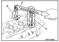
4. Remove valve collet.
• Compress valve spring with the valve spring compressor [SST: KV10116200 (J-26336-A)] (A), the attachment [SST: KV10115900 (J-26336-20)] (C), and the adapter [SST: KV10109220 ( — )] (B). Remove valve collet with magnet hand.
CAUTION:
Be careful not to damage valve lifter holes.
5. Remove valve spring retainer and valve spring (with valve spring seat).
CAUTION:
Never remove valve spring seat from valve spring.
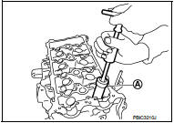
6. Remove valve oil seal with the valve oil seal puller [SST: KV10107902 (J-38959)] (A).
INSTALLATION
1. Apply new engine oil to valve oil seal joint surface and seal lip.
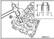
2. Press in valve oil seal to the height (H) shown in the figure with the valve oil seal drift [SST: KV10115600 (J-38958)] (A).
Height (H) : 15.1 - 15.7 mm (0.594 - 0.618 in)
3. Install in the reverse order of removal, for the rest of parts.
 Oil seal
...
 Front oil seal
FRONT OIL SEAL : Removal and Installation
REMOVAL
1. Remove the following parts.
• Front fender protector (RH): Refer to EXT-22, "Exploded View".
• Drive belt: Refer to EM-20, " ...
Other materials:
Intelligent Cruise Control (ICC) (for vehicles without ProPILOT Assist)
WARNING
Failure to follow these safety warnings and operational instructions regarding the Intelligent Cruise Control (ICC) system could lead to a loss of vehicle control, resulting in serious injury or death.
The ICC system is designed strictly as a driving ...
Antenna
To remove the antenna, hold the bottom of the antenna and turn it counterclockwise.
To install the antenna, turn the antenna clockwise and tighten.
CAUTION
• To avoid damaging or deforming the antenna, be sure to fold down (if so
equipped) or remove the antenna under the following condition ...
Inspection
OIL LEAKAGE
Check rear final drive surrounding area (oil seal, drain plug, filler plug,
and carrier case, etc.) for oil leakage.
OIL LEVEL
1. Remove filler plug (1) and check oil level from filler plug mounting
hole as shown in the figure.
CAUTION:
Never start engine while checking oil l ...
