Nissan Juke Service and Repair Manual : U1000 can comm circuit
Description
CAN (Controller Area Network) is a serial communication system for real time application. It is an on-vehicle multiplex communication system with high data communication speed and excellent error detectability. Many electronic control units are equipped onto vehicles, and each control unit shares information and links with other control units during operation (not independent). In CAN communication, control units are connected with two communication lines (CAN-H line, CAN-L line) allowing a high rate of information transmission with less wiring. Each control unit transmits/receives data but selectively reads required data only.
CAN Communication Signal Chart. Refer to LAN-31, "CAN COMMUNICATION SYSTEM : CAN Communication Signal Chart"
DTC Logic
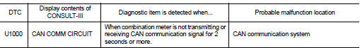
DTC DETECTION LOGIC
Diagnosis Procedure
1.PERFORM SELF DIAGNOSTIC
1. Turn ignition switch ON and wait for 2 seconds or more.
2. Check “Self Diagnostic Result” of “METER/M&A”.
Is “CAN COMM CIRCUIT” displayed? YES >> Refer to LAN-17, "Trouble Diagnosis Flow Chart".
NO >> Refer to GI-42, "Intermittent Incident".

 U1010 control unit (can)
Description
Initial diagnosis of combination meter.
DTC Logic
DTC DETECTION LOGIC
Diagnosis Procedure
1.REPLACE COMBINATION METER
When DTC “U1010” is detected, replace combination meter.
...
Other materials:
Vehicle Dynamic Control (VDC) off switch
The vehicle should be driven with the Vehicle Dynamic Control (VDC) system on
for most driving conditions.
If the vehicle is stuck in mud or snow, the VDC system reduces the engine output
to reduce wheel spin. The engine speed will be reduced even if the accelerator is
depressed to the floo ...
Windows
Power windows
WARNING
Ensure that all passengers have their hands, fingers, and other belongings safely inside the vehicle while it is in motion and before operating the controls to close the windows. It is highly recommended to use the integrated window lock switch to prevent an ...
Brake pad wear warning
The disc brake pads have audible wear warnings.
When a brake pad requires replacement, it will make a high pitched scraping sound
when the vehicle is in motion. This scraping sound will first occur only when the
brake pedal is depressed. After more wear of the brake pad, the sound will always
...
