Nissan Juke Service and Repair Manual : Rear wiper arm
Exploded View
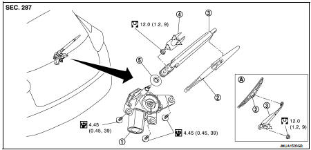
1. Rear wiper motor
2. Rear wiper blade
3. Rear wiper arm
4. Rear wiper arm cover
5. Rear wiper pivot seal
A : Model for cold areas
 : Pawl
 : N·m (kg-m, in-lb)
 : N·m (kg-m, ft-lb)
Removal and Installation
REMOVAL
1. Operate rear wiper to the auto stop position.
2. Remove rear wiper arm cover.
3. Remove rear wiper arm mounting nut.
4. Remove wiper arm from the vehicle.
INSTALLATION
1. Clean wiper arm mount as shown in the figure to prevent nut from being loosened.
2. Operate the rear wiper motor to the auto stop position.
3. Adjust the rear wiper blade position. Refer to WW-84, "Adjustment".
4. Install the rear wiper arm by tightening the mounting nut.
5. Inject the washer fluid.
6. Operate the rear wiper to the auto stop position.
7. Check that the rear wiper blades stop at the specified position.
8. Install the rear wiper arm cover.
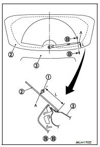
Adjustment
REAR WIPER BLADE POSITION ADJUSTMENT
Set the wiper blade top on the defrosting wire (A) (clearance between the end of back door glass and the top of wiper blade center).
Standard clearance
1. Rear wiper blade
2. Back door window glass
3. Back door panel
A : Rear defogger wire print
L : 67.5 ± 7.5 mm (2.657 ± 0.295in)
 Wiper and washer switch
Exploded View
The washer level switch must be replaced together with the washer tank as an
assembly. Refer to WW-67,
"Removal and Installation". ...
 Rear wiper motor
Exploded View
1. Rear wiper motor
2. Rear wiper blade
3. Rear wiper arm
4. Rear wiper arm cover
5. Rear wiper pivot seal
A : Model for cold areas
: Pawl
: N·m (kg-m, in-lb)
: N·m (kg-m ...
Other materials:
Rear door lock
Exploded View
1. Outside handle assembly
2. Inside handle
3. TORX bolt
4. Door lock assembly
5. Rear door sealing screen
: Clip
: Pawl
: Vehicle front
: Do not reuse
: N·m (kg-m, in-lb)
: Body grease
Door lock
DOOR LOCK : Removal and Installation
REMOVAL
1. Remove rear door glas ...
Insufficient heating
Description
Symptom
• Insufficient heating
• No warm air comes out. (Air flow volume is normal.)
Diagnosis Procedure
NOTE:
Perform self-diagnosis with CONSULT-III before performing symptom diagnosis. If
any malfunction result or
DTC is detected, perform the corresponding diagnosis.
1 ...
Super lock actuator
Driver side : Component Function Check
1.CHECK FUNCTION
1. Select “DOOR LOCK” of “BCM” using CONSULT-III.
2. Select “SUPER LOCK” in “ACTIVE TEST” mode.
3. Check that the function operates normally according to the following
conditions.
Is the inspection result normal?
YES & ...
