Nissan Juke Service and Repair Manual : U0155 lost communication (IPC)
Description
CAN (Controller Area Network) is a serial communication line for real-time application. It is an on-vehicle multiplex communication line with high data communication speed and excellent malfunction detection ability.
Many electronic control units are equipped onto a vehicle, and each control unit shares information and links with other control units during operation (not independently). In CAN communication, control units are connected with 2 communication lines (CAN-H line, CAN-L line) allowing a high rate of information transmission with less wiring. Each control unit transmits/receives data but selectively reads required data only.
DTC Logic
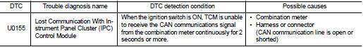
DTC DETECTION LOGIC
DTC CONFIRMATION PROCEDURE
1.PREPARATION BEFORE WORK
If another “DTC CONFIRMATION PROCEDURE” occurs just before, turn ignition switch OFF and wait for at least 10 seconds, then perform the next test.
>> GO TO 2.
2.PERFORM DTC CONFIRMATION PROCEDURE
 With CONSULT-III
1. Start the engine and wait for at least 5 seconds.
2. Check the DTC.
Is “U0155” detected? YES >> Go to TM-388, "Diagnosis Procedure".
NO >> INSPECTION END
Diagnosis Procedure
For the diagnosis procedure, refer to LAN-17, "Trouble Diagnosis Flow Chart".
 U0141 lost communication (BCM A)
Description
CAN (Controller Area Network) is a serial communication line for real-time
application. It is an on-vehicle multiplex
communication line with high data communication speed and excellen ...
 U0300 can communication data
Description
CAN (Controller Area Network) is a serial communication line for real-time
application. It is an on-vehicle multiplex
communication line with high data communication speed and excellen ...
Other materials:
Key switch
Component Function Check
1.CHECK FUNCTION
1. Select “DOOR LOCK” of “BCM” using CONSULT-III.
2. Select “KEY ON SW” in “DATA MONITOR” mode.
3. Check that the function operates normally according to the following
conditions.
Is the inspection result normal?
YES >> Key sw ...
Malfunction indicator lamp
Component Function Check
1.CHECK MIL FUNCTION
1. Turn ignition switch ON.
2. Check that MIL lights up.
Is the inspection result normal?
YES >> INSPECTION END
NO >> Proceed to EC-436, "Diagnosis Procedure".
Diagnosis Procedure INFOID:0000000006547250
1.CHECK DTC
Che ...
Thermo control amplifier
Removal and Installation
REMOVAL
1. Remove evaporator.
• Refer to HA-55, "EVAPORATOR : Removal and Installation". (HR16DE)
• Refer to HA-115, "EVAPORATOR : Removal and Installation". (MR16DDT)
2. Remove the thermo control amp. from evaporator.
INSTALLATION
Note the ...
