Nissan Juke Service and Repair Manual : Adjustment of steering angle sensor neutral position
Description
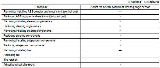
Always adjust the neutral position of steering angle sensor before driving when the following operation is performed.
Work Procedure
ADJUST THE NEUTRAL POSITION OF STEERING ANGLE SENSOR
CAUTION:
Always use CONSULT-III when adjusting the neutral position of steering angle
sensor. (It cannot be
adjusted other than with CONSULT-III.)
1.CHECK THE VEHICLE STATUS
Stop vehicle with front wheels in the straight-ahead position.
Does the vehicle stay in the straight-ahead position? YES >> GO TO 2.
NO >> Steer the steering wheel to the straight-ahead position. Stop the vehicle.
2.ADJUST NEUTRAL POSITION OF STEERING ANGLE SENSOR
 With CONSULT-III.
1. Turn the ignition switch ON.
CAUTION:
Never start engine.
2. Select “ABS”, “WORK SUPPORT” and “ST ANGLE SENSOR ADJUSTMENT” in this order.
3. Select “START”.
CAUTION:
Never touch steering wheel while adjusting steering angle sensor.
4. After approx. 10 seconds, select “END”.
5. Turn ignition switch OFF, and then turn it ON again.
CAUTION:
Be sure to perform the operation above.
>> GO TO 3.
3.CHECK DATA MONITOR
 With CONSULT-III.
1. The vehicle is either pointing straight ahead, or the vehicle needs to be moved. Stop when it is pointing straight ahead.
2. Select “ABS”, “DATA MONITOR”, “ECU INPUT SIGNALS” and “STR ANGLE SIG” in the order. Check that the signal is within the specified value.
STR ANGLE SIG : 0±2.5°
Is the inspection result normal? YES >> GO TO 4.
NO >> GO TO 1.
4.ERASE SELF-DIAGNOSIS MEMORY
With CONSULT-III.
Erase Self-diagnosis result of “ABS”.
Are the memories erased? YES >> INSPECTION END
NO >> Check the items indicated by the self-diagnosis.
 Additional service when replacing ABS actuator and electric
unit (control unit)
Additional service when replacing ABS actuator and electric
unit (control unit)
Description
When replaced the ABS actuator and electric unit (control unit), Perform
decel G sensor calibration. Refer to
BRC-149, "Work Procedure". ...

Other materials:
C1111 ABS motor, motor relay system
DTC Logic
DTC DETECTION LOGIC
DTC CONFIRMATION PROCEDURE
1.PRECONDITIONING
If “DTC CONFIRMATION PROCEDURE” has been previously conducted, always turn
ignition switch OFF and
wait at least 10 seconds before conducting the next test.
>> GO TO 2.
2.CHECK DTC DETECTION
With CON ...
P0409 EGR volume control valve control position sensor
DTC Logic
DTC DETECTION LOGIC
Diagnosis Procedure
1.CHECK GROUND CONNECTIONS
1. Turn ignition switch OFF.
2. Check ground connection E38. Refer to Ground inspection in GI-44, "Circuit
Inspection".
Is the inspection result normal?
YES >> GO TO 2.
NO >> Repair or ...
Front door
Exploded View
1. Front door panel
2. Grommet
3. TORX bolt
4. Door striker
5. Door pad
6. Bumper rubber
7. Door check link
8. Door hinge (lower)
9. Door hinge (upper)
10. Grommet
: Do not reuse
: N·m (kg-m, in-lb)
: N·m (kg-m, ft-lb)
: Body grease
Door assembly
DOOR ASSEMBLY ...
