Nissan Juke Service and Repair Manual : P0560 battery voltage
DTC Logic
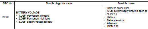
DTC DETECTION LOGIC
NOTE
:
When IPDM E/R DTC is indicated with DTC P0560, IPDM E/R DTC must be checked
first.
Diagnosis Procedure
1.CHECK BATTERY VOLTAGE
1. Turn ignition switch ON.
2. Check battery voltage.
Voltage: Above 11 V
Is the inspection result normal? YES >> GO TO 2.
NO >> Recharge the battery.
2.CHECK BATTERY TERMINALS
1. Turn ignition switch OFF.
2. Check battery terminals condition.
Is the inspection result normal? YES >> GO TO 3.
NO >> Repair the battery terminals.
3.CHECK BATTERY AND ALTERNATOR
Check that the proper type of battery and type of alternator are installed.
Refer to, PG-126, "Battery" and CHG-35, "Alternator".
Is the inspection result normal? YES >> GO TO 4.
NO >> Replace with a proper one.
4.CHECK ECM POWER SUPPLY CIRCUIT-I
Check the voltage between ECM harness connector and ground.
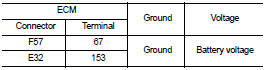
Is the inspection result normal? YES >> GO TO 8.
NO >> GO TO 5.
5.CHECK ECM POWER SUPPLY CIRCUIT-II
1. Disconnect ECM harness connector.
2. Disconnect IPDM E/R harness connector E14.
3. Check the continuity between ECM harness connector and IPDM E/R harness connector
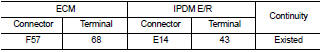
4. Also check harness for short to ground and short to power.
Is the inspection result normal? YES >> GO TO 7.
NO >> GO TO 6.
6.DETECT MALFUNCTIONING PART
Check the following.
• Harness connectors E8, F1 • Harness for open or short between ECM and IPDM E/R
>> Repair open circuit or short to ground or short to power in harness or connectors.
7.CHECK 20A FUSE
1. Disconnect 20A fuse (No. 43) from IPDM E/R.
2. Check 20A fuse.
Is the inspection result normal? YES >> GO TO 8.
NO >> Replace 20A fuse.
8.CHECK INTERMITTENT INCIDENT
Refer to GI-42, "Intermittent Incident", ???INCIDENT SIMULATION TESTS??? and ???GROUND INSPECTION???.
Is the inspection result normal? YES >> Replace IPDM E/R.
NO >> Repair or replace.
 P0544 EGT sensor 1
DTC Logic
DTC DETECTION LOGIC
Diagnosis Procedure
1.CHECK GROUND CONNECTIONS
1. Turn ignition switch OFF.
2. Check ground connection E38. Refer to Ground inspection in GI-44, "Circuit
In ...
 P0564 ASCD steering switch
DTC Logic
DTC DETECTION LOGIC
Diagnosis Procedure
1.CHECK ASCD STEERING SWITCH CIRCUIT
1. Check ASCD steering switch circuit.
ASCD steering switch>>Refer to EC-1011, "Component Fun ...
Other materials:
Refilling
1. Remove filler plug (1). Fill with new gear oil until oil level reaches
the specified level near filler plug mounting hole
Oil grade and viscosity : Refer to MA-13, "Fluids
and Lubricants".
Oil capacity : Refer to DLN-167, "General
Specification".
2. After refilling oil, ...
Headlamp (LO) circuit
Component Function Check
1.CHECK HEADLAMP (LO) OPERATION
CONSULT-III ACTIVE TEST
1. Select “EXTERNAL LAMPS” of IPDM E/R active test item.
2. With operating the test items, check that the headlamp (LO) is turned ON.
Lo : Headlamp (LO) ON
Off : Headlamp (LO) OFF
Is the inspection result nor ...
Precautions for Harness Repair
• Solder the repaired area and wrap tape around the soldered area.
NOTE:
A fray of twisted lines must be within 110 mm (4.33 in).
• Bypass connection is never allowed at the repaired area.
NOTE:
Bypass connection may cause CAN communication error. The
spliced wire becomes separated a ...
