Nissan Juke Service and Repair Manual : Diagnosis system (combination meter)
On Board Diagnosis Function
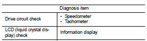
ON BOARD DIAGNOSIS ITEM
The combination meter allows the following diagnosis items with the on-board diagnosis function.
METHOD OF STARTING
1. Turn ignition switch ON, and switch the trip meter to “trip A” or “trip B”.
2. Turn ignition switch OFF.
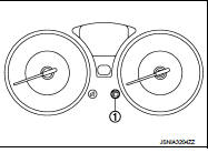
3. While pressing the meter control switch (1), turn ignition switch ON.
4. Make sure that the trip meter displays “0000.0”.
5. Press the meter control switch at least 3 times. (Within 7 seconds after the ignition switch is turned ON.)
6. The combination meter is turned to self-diagnosis mode.
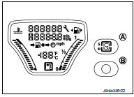
All of the segments of engine coolant temperature gauge, fuel gauge, odo/trip meter, shift position indicator (A) for CVT models and information display illuminate.
NOTE
:
• Check combination meter power supply and ground circuit
when the self-diagnosis mode of the combination meter does
not start. Replace combination meter if power supply and
ground circuit are normal.
• If any of the dots are not displayed, replace combination meter.
• For M/T models, start-up lamp (B) illuminate instead of shift position indicator.
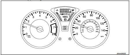
7. Each meter activates by pressing the meter control switch.
NOTE
:
• If any of the meters or gauges is not activated, replace combination meter.
• The figure is reference.
Consult-III Function
CONSULT-III APPLICATION ITEMS
CONSULT-III can perform the following diagnosis modes via CAN communication and the combination meter.
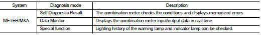
SELF DIAG RESULT
Refer to MWI-36, "DTC Index".
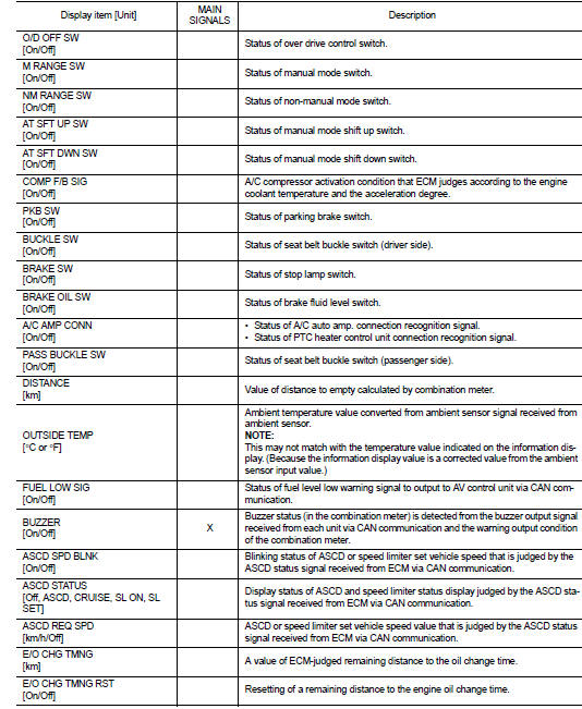
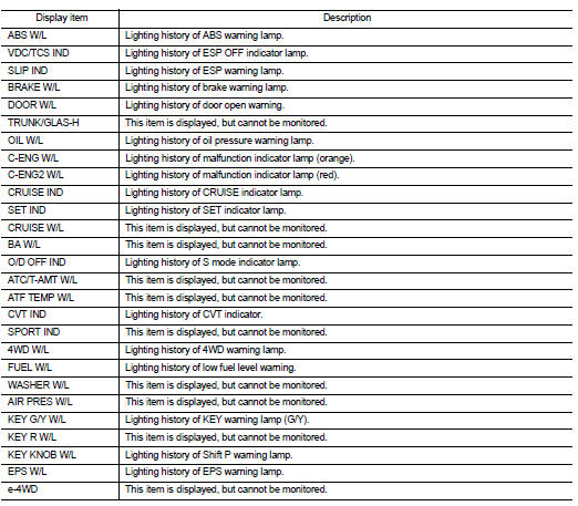
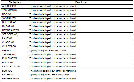
DATA MONITOR
Display Item List
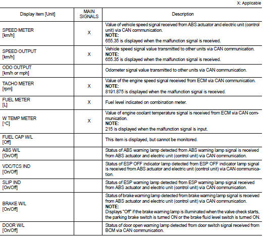
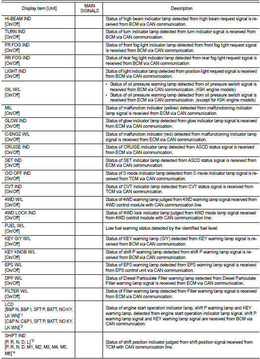
• *1: CVT models
• *2: M/T models
• *3: Without manual mode CVT
• *4: With manual mode CVT
NOTE
:
Some items are not available according to vehicle specification.
SPECIAL FUNCTION
Special menu

W/L ON HISTORY
• Stores histories when warning/indicator lamp is turned on.
• “W/L ON HISTORY” indicates the “TIME” when the warning/ indicator lamp is turned on.
• The “TIME” above is:
- 0: The condition that the warning/indicator lamp has been turned on 1 or more
times after starting the engine
and waiting for 30 seconds.
- 1 - 39: The number of times the engine was restarted after the 0 condition.
- NO W/L ON HISTORY: Stores NO (0) turning on history of warning/indicator lamp.
NOTE
:
• W/L ON HISTORY is not stored for approximately 30 seconds after the engine
starts.
• Brake warning lamp does not store any history when the parking brake is applied or the brake fluid level gets low.
Display Item
 Operation
Switch Name and Function
...

Other materials:
Not communication with the ECM
Description
CHART 1: NO COMMUNICATION WITH THE ECM
Diagnosis Procedure
1.INSPECTION START
Ensure that CONSULT-III is not causing the malfunction by trying to establish
dialogue with an ECM on
another vehicle. If the CONSULT-III is not at malfunction, and dialogue cannot
be established with ...
Precaution Necessary for Steering Wheel Rotation after Battery Disconnect
NOTE:
• Before removing and installing any control units, first turn the ignition
switch to the LOCK position, then disconnect
both battery cables.
• After finishing work, confirm that all control unit connectors are connected
properly, then re-connect both
battery cables.
• Always us ...
Vehicle Dynamic Control (VDC) off switch
The vehicle should be driven with the Vehicle Dynamic Control (VDC) system on
for most driving conditions.
If the vehicle is stuck in mud or snow, the VDC system reduces the engine output
to reduce wheel spin. The engine speed will be reduced even if the accelerator is
depressed to the floo ...
