Nissan Juke Service and Repair Manual : Transmission range switch
Exploded View
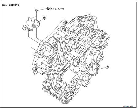
1. Transmission range switch 2. Transaxle assem
Removal and Installation
REMOVAL
1. Remove battery. Refer to PG-124, "Removal and Installation".
2. Remove transmission range switch connector.
3. Remove control cable. Refer to TM-273, "Removal and Installation".
4. Remove transmission range switch from transaxle assembly.
INSTALLATION
Install in the reverse order of removal.
Inspection and Adjustment
ADJUSTMENT OF TRANSMISSION RANGE SWITCH
1. Move selector lever to “N” position.
2. Remove control cable from manual lever.
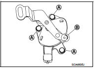
3. Loosen mounting bolts (A) of transmission range switch. Insert a pin (φ4 mm) into the adjusting holes (B) on both transmission range switch and manual lever for adjusting the position.
4. Tighten mounting bolts of transmission range switch.
5. Connect control cable on manual lever. Refer to TM-194, "Inspection and Adjustment".
ADJUSTMENT AFTER INSTALLATION
Adjust the CVT positions after installing the CVT shift selector. Refer to TM-194, "Inspection and Adjustment".
INSPECTION AFTER INSTALLAION
Check the CVT positions after adjusting the CVT positions. Refer to TM-194, "Inspection and Adjustment".
 Key interlock cable
Exploded View
1. CVT shift selector assembly
2. Key interlock cable
A: Key cylinder
B: Clip
C: Clip
Removal and Installation
REMOVAL
CAUTION:
Always apply the parking brake before perfor ...
 TCM
TCM
Exploded View
1. Bracket
2. TCM
:Vehicle front
: N·m (kg-m, in-lb)
Removal and Installation
NOTE:
When replacing TCM and transaxle assembly as a set, replace transaxle assembly
first and ...
Other materials:
Diagnosis system (bcm) (with intelligent key system)
Common item
COMMON ITEM : CONSULT-III Function (BCM - COMMON ITEM)
APPLICATION ITEM
CONSULT-III performs the following functions via CAN communication with BCM.
SYSTEM APPLICATION
BCM can perform the following functions for each system.
NOTE:
It can perform the diagnosis modes except the ...
Headlamp aiming system (manual)
Component Inspection
1.CHECK HEADLAMP AIMING SWITCH
1. Remove headlamp aiming switch.
2. Check resistance among each headlamp aiming switch terminal.
Is the inspection result normal?
YES >> Headlamp aiming switch is normal.
NO >> Replace the headlamp aiming switch.
...
High voltage precautions
High-voltage components
WARNING
The advanced electric vehicle (EV) system in your Nissan Leaf operates using high-voltage electricity, reaching levels up to approximately 400 volts DC. Please be aware that these internal components can remain extremely hot during operation, immed ...
