Nissan Juke Service and Repair Manual : Super lock actuator
Driver side : Component Function Check
1.CHECK FUNCTION
1. Select “DOOR LOCK” of “BCM” using CONSULT-III.
2. Select “SUPER LOCK” in “ACTIVE TEST” mode.
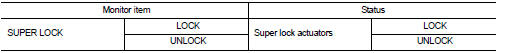
3. Check that the function operates normally according to the following conditions.
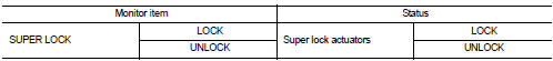
Is the inspection result normal? YES >> Super lock actuator is OK.
NO >> Refer to DLK-99, "DRIVER SIDE : Diagnosis Procedure".
Driver side : Diagnosis Procedure
1.CHECK SUPER LOCK ACTUATOR INPUT SIGNAL
1. Turn ignition switch OFF.
2. Disconnect front door lock assembly (driver side) connector.
3. Check voltage between front door lock assembly (driver side) harness connector and ground.
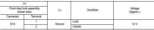
Is the inspection result normal? YES >> Replace front door lock assembly (driver side).
NO >> GO TO 2.
2.CHECK SUPER LOCK ACTUATOR CIRCUIT
1. Disconnect BCM connector and all door lock assembly connector.
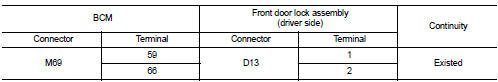
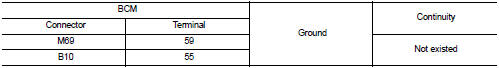
2. Check continuity between BCM harness connector and front door lock assembly (driver side) harness connector.
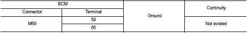
3. Check continuity between BCM harness connector and ground
Is the inspection result normal? YES >> GO TO 3.
NO >> Repair or replace harness.
3.CHECK BCM OUTPUT SIGNAL
1. Connect BCM connector.
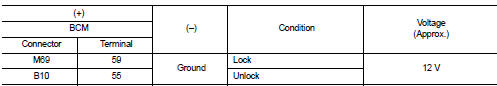
2. Check voltage between BCM harness connector and ground.
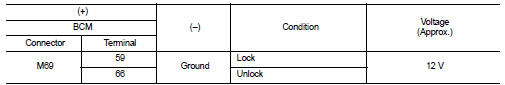
Is the inspection result normal? YES >> Check for internal short of each super lock actuator.
NO >> Replace BCM. Refer to BCS-93, "Removal and Installation".
Passenger side : Component Function Check
1.CHECK FUNCTION
1. Select “DOOR LOCK” of “BCM” using CONSULT-III.
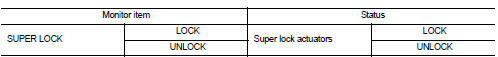
2. Select “SUPER LOCK” in “ACTIVE TEST” mode.
3. Check that the function operates normally according to the following conditions.
Is the inspection result normal? YES >> Super lock actuator is OK.
NO >> Refer to DLK-100, "PASSENGER SIDE : Diagnosis Procedure".
Passenger side : Diagnosis Procedure
1.CHECK SUPER LOCK ACTUATOR INPUT SIGNAL
1. Turn ignition switch OFF.
2. Disconnect front door lock assembly (passenger side) connector.
3. Check voltage between front door lock assembly (passenger side) harness connector and ground.
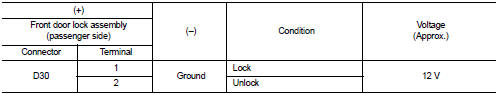
Is the inspection result normal? YES >> Replace front door lock assembly (passenger side).
NO >> GO TO 2.
2.CHECK SUPER LOCK ACTUATOR CIRCUIT
1. Disconnect BCM connector and all door lock assembly connector.
2. Check continuity between BCM harness connector and front door lock assembly (passenger side) harness connector
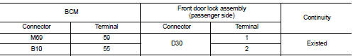
3. Check continuity between BCM harness connector and ground.
Is the inspection result normal? YES >> GO TO 3.
NO >> Repair or replace harness.
3.CHECK BCM OUTPUT SIGNAL
1. Connect BCM connector.
2. Check voltage between BCM harness connector and ground.
Is the inspection result normal? YES >> Check for internal short of each super lock actuator.
NO >> Replace BCM. Refer to BCS-93, "Removal and Installation".
Rear LH : Component Function Check
1.CHECK FUNCTION
1. Select “DOOR LOCK” of “BCM” using CONSULT-III.
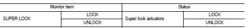
2. Select “SUPER LOCK” in “ACTIVE TEST” mode.
3. Check that the function operates normally according to the following conditions.
Is the inspection result normal? YES >> Super lock actuator is OK.
NO >> Refer to DLK-101, "REAR LH : Diagnosis Procedure".
Rear LH : Diagnosis Procedure
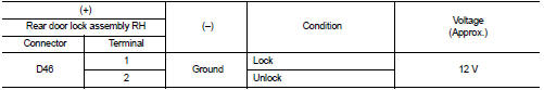
1.CHECK SUPER LOCK ACTUATOR INPUT SIGNAL
1. Turn ignition switch OFF.
2. Disconnect rear door lock assembly LH connector.
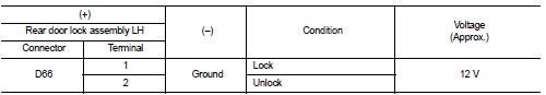
3. Check voltage between rear door lock assembly LH harness connector and ground.
Is the inspection result normal? YES >> Replace rear door lock assembly LH.
NO >> GO TO 2.
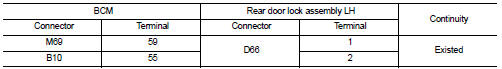
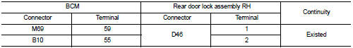
2.CHECK SUPER LOCK ACTUATOR CIRCUIT
1. Disconnect BCM connector and all door lock assembly connector.
2. Check continuity between BCM harness connector and rear door lock assembly LH harness connector.
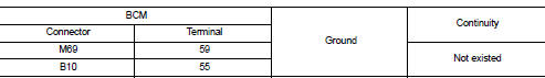
3. Check continuity between BCM harness connector and ground
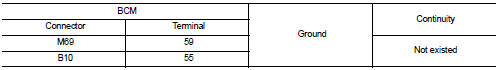
Is the inspection result normal? YES >> GO TO 3.
NO >> Repair or replace harness.
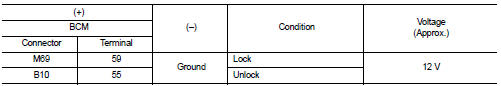
3.CHECK BCM OUTPUT SIGNAL
1. Connect BCM connector.
2. Check voltage between BCM harness connector and ground.
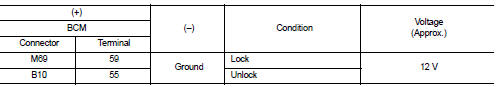
Is the inspection result normal? YES >> Check for internal short of each super lock actuator.
NO >> Replace BCM. Refer to BCS-93, "Removal and Installation".
Rear RH : Component Function Check
1.CHECK FUNCTION
1. Select “DOOR LOCK” of “BCM” using CONSULT-III.
2. Select “SUPER LOCK” in “ACTIVE TEST” mode.
3. Check that the function operates normally according to the following conditions.
Is the inspection result normal? YES >> Back door lock actuator is OK.
NO >> Refer to DLK-103, "REAR RH : Diagnosis Procedure".
Rear RH : Diagnosis Procedure
1.CHECK SUPER LOCK ACTUATOR INPUT SIGNAL
1. Turn ignition switch OFF.
2. Disconnect rear door lock assembly RH connector.
3. Check voltage between rear door lock assembly RH harness connector and ground.
Is the inspection result normal? YES >> Replace rear door lock assembly RH.
NO >> GO TO 2.
2.CHECK SUPER LOCK ACTUATOR CIRCUIT
1. Disconnect BCM connector and all door lock assembly connector.
2. Check continuity between BCM harness connector and rear door lock assembly RH harness connector.
3. Check continuity between BCM harness connector and ground.
Is the inspection result normal? YES >> GO TO 3.
NO >> Repair or replace harness.
3.CHECK BCM OUTPUT SIGNAL
1. Connect BCM connector.
2. Check voltage between BCM harness connector and ground.
Is the inspection result normal? YES >> Check for internal short of each super lock actuator.
NO >> Replace BCM. Refer to BCS-93, "Removal and Installation".
 Shift P warning lamp
Component Function Check
1.CHECK FUNCTION
1. Select “INTELLIGENT KEY” of “BCM” using CONSULT-III.
2. Select “LCD” in “ACTIVE TEST” mode.
3. Check that the function operates normall ...
 Unlock sensor
Component Function Check
1.CHECK FUNCTION
1. Select “INTELLIGENT KEY” of “BCM” using CONSULT-III.
2. Select “UNLK SEN -DR” in “DATA MONITOR” mode.
3. Check that the function operat ...
Other materials:
Key reminder function does not operate
Diagnosis Procedure
1.CHECK DTC WITH BCM
Check that DTC is not detected with BCM.
Is the inspection result normal?
YES >> GO TO 2.
NO >> Refer to BCS-67, "DTC Index".
2.CHECK “ANTI KEY LOCK IN FUNCTI” SETTING IN “WORK SUPPORT”
1. Select “INTELLIGENT KEY†...
Back door opener system
System Diagram
System Description
BACK DOOR OPENER OPERATION
When back door opener switch is pressed, BCM operates back door opener
actuator.
NOTE:
Back door opener actuator is not for locking the back door. The function is only
to open the back door.
OPERATION CONDITION
If the foll ...
Front and rear outboard seat-mounted side-impact supplemental air bag and roof-mounted curtain side-impact and rollover supplemental air bag systems
The side-impact air bags are integrated into the outer sections of the front seatbacks and the rear outboard seatbacks, while the protective curtain air bags are housed within the vehicle's side roof rails. All safety protocols, cautions, and operational guidelines outlined in ...
