Nissan Juke Service and Repair Manual : Side oil seal
Exploded View
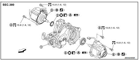
1. Rear final drive assembly
2. Side oil seal (right)
3. Electric controlled coupling (right)
4. Reamer bolt
5. Side oil seal (left)
6. Electric controlled coupling (left)
A. Oil seal lip B. Gear carrier mouting face
 : Vehicle front
 : N·m (kg-m, ft-lb)
 : Always replace after every
disassembly.
 : Apply multi purpose grease
 : Apply gear oil.
 : Apply Genuine Liquid Gasket 1217
or equivalent.
Removal and Installation
REMOVAL
1. Remove electric controlled couplings. Refer to DLN-139, "Removal and Installation".
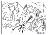
2. Remove side oil seals with a suitable tool.
CAUTION:
Never damage gear carrier and rear cover.
INSTALLATION
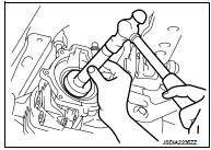
1. Install side oil seal (right side) until it becomes flush with the carrier end, using the drift (A) (SST: KV38100200).
CAUTION:
• Never reuse oil seals.
• When installing, never incline oil seals.
• Apply multi-purpose grease onto oil seal lips, and gear oil onto the circumference of oil seal
.
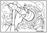
2. Install side oil seal (left side) until it becomes flush with the carrier end, using the drift (A) (SST: KV38100500).
CAUTION:
• Never reuse oil seals.
• When installing, never incline oil seals.
• Apply multi-purpose grease onto oil seal lips, and gear oil onto the circumference of oil seal.
3. Install electric controlled couplings. Refer to DLN-139, "Removal and Installation".
4. When oil leaks while removing, check oil level after the installation.
Refer to DLN-132, "Inspection".
 Front oil seal
Exploded View
1. Rear final drive assembly
2. Front oil seal
3. Companion flange
4. Companion flange lock nut
A. Oil seal lip
: Vehicle front
: N·m (kg-m, ft-lb)
: Never reuse parts
: Ap ...
 Electric controlled coupling
Exploded View
1. Sub-harness
2. Rear final drive assembly
3. Electric controlled coupling (right)
4. Reamer bolt
5. Electric controlled coupling (left)
A. Gear carrier mouting face
: Vehic ...
Other materials:
Ignition signal
Component Function Check
1.INSPECTION START
Turn ignition switch OFF, and restart engine.
Does the engine start?
YES-1 >> With CONSULT-III: GO TO 2.
YES-2 >> Without CONSULT-III: GO TO 3.
NO >> Go to EC-783, "Diagnosis Procedure".
2.IGNITION SIGNAL FUNCTION ...
Power supply and ground circuit
PTC HEATER CONTROL UNIT : Diagnosis Procedure
1.CHECK FUSE
1. Turn ignition switch OFF.
2. Check 10A fuses (No. 3 and 7).
NOTE:
Refer to PG-23, "Fuse and Fusible Link Arrangement".
Is the inspection result normal?
YES >> GO TO 2.
NO >> Replace the blown fuse after ...
Lower link
Exploded View
1. Rear suspension member
2. Adjusting bolt
3. Upper link
4. Eccentric disk
5. Lower link
6. Suspension arm bracket
7. Suspension arm
: Vehicle front
: Always replace after every
disassembly.
: N·m (kg-m, ft-lb)
Removal and Installation
REMOVAL
1. Remove tires. Re ...
