Nissan Juke Service and Repair Manual : Front oil seal
Exploded View
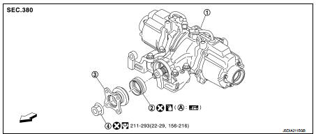
1. Rear final drive assembly
2. Front oil seal
3. Companion flange
4. Companion flange lock nut
A. Oil seal lip
 : Vehicle front
 : N·m (kg-m, ft-lb)
 : Never reuse parts
 : Apply multi purpose grease
 : Apply gear oil.
Removal and Installation
REMOVAL
CAUTION:
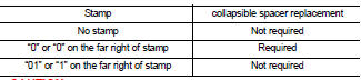
Verify identification stamp of replacement frequency put in the lower part of
gear carrier to determine
replacement for collapsible spacer when replacing front oil seal. Refer to
“Identification stamp of
replacement frequency of front oil seal”. If collapsible spacer replacement is
necessary, remove final
drive assembly and disassemble it to replace front oil seal and collapsible
spacer. Refer to DLN-144,
"Removal and Installation" and DLN-160, "Disassembly".
NOTE:
The reuse of collapsible spacer is prohibited in principle. However, it is reusable on a one-time basis only in cases when replacing front oil seal.
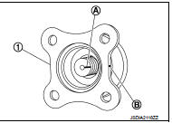
Identification stamp of replacement frequency of front oil seal
• The diagonally shaded area in the figure shows stamping point for replacement frequency of front oil seal.
• The following table shows if collapsible spacer replacement is needed before replacing front oil seal.
When collapsible spacer replacement is required, disassemble final drive assembly to replace collapsible spacer and front oil seal.
Refer to DLN-160, "Disassembly".
CAUTION:
Make a stamping after replacing front oil seal.
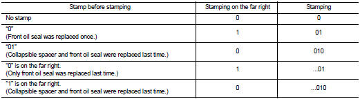
• After replacing front oil seal, make a stamping on the stamping point in accordance with the table below in order to identify replacement frequency.
CAUTION:
Make a stamping from left to right.
1. Make a judgment if a collapsible spacer replacement is required.
2. Remove rear propeller shaft. Refer to DLN-121, "Removal and Installation".
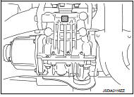
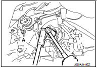
3. Measure the total preload with the preload gauge (A) (SST: ST3127S000).
NOTE
:
Record the preload measurement.
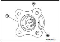
4. Put matching mark (B) on the end of the drive pinion. The matching mark (B) should be in line with the matching mark (A) on companion flange (1).
CAUTION:
For matching mark, use paint. Never damage companion
flange and drive pinion.
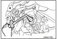
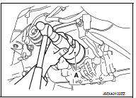
5. Remove companion flange lock nut using the flange wrench (A) (commercial service tool).
6. Remove companion flange using pullers (A) (commercial service tool).
7. Remove front oil seal using a suitable tool.
CAUTION:
Never damage carrier case.
INSTALLATION
1. Apply multi-purpose grease to front oil seal lips.
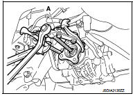
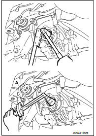
2. Install front oil seal using the drift (A) (commercial service tool) as shown in figure.
CAUTION:
• Never reuse oil seal.
• Never incline oil seal when installing.
3. Align the matching mark (B) of drive pinion with the matching mark (A) of companion flange (1), and then install the companion flange (1).
4. Temporarily tighten drive pinion lock nut to drive pinion, using flange wrench (commercial service tool).
CAUTION:
• Never reuse drive pinion lock nut.
• Apply anti-corrosion oil to the thread and seat of new drive pinion lock nut.
5. Tighten drive pinion lock nut within the limits of specified torque so as to keep the pinion bearing preload within a standard values, using preload gauge (A) (SST: ST3127S000).
Total preload torque : A value that add 0.1 – 0.4 N·m (0.01 – 0.04 kg-m, 0.1 – 0.3 in-lb) to the measured value before removing.
CAUTION:
• Adjust to the lower limit of the drive pinion lock nut tightening
torque first.
• If the preload torque exceeds the specified value, replace collapsible spacer and tighten it again to adjust. Never loosen drive pinion lock nut to adjust the preload torque.
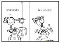
6. Fit a dial indicator onto the companion flange face (inner side of the rear propeller shaft mounting bolt holes).
7. Rotate companion flange to check for runout.
Companion flange runout : Refer toDLN-167, "Companion Flange Runout".
8. Fit a test indicator to the inner side of companion flange (socket diameter).
9. Rotate companion flange to check for runout.
Companion flange runout : Refer toDLN-167, "Companion Flange Runout".
10. If the runout value is outside the runout limit, follow the procedure below to adjust.
a. Check for runout while changing the phase between companion flange and drive pinion by 90° step, and search for the position where the runout is the minimum.
b. If the runout value is still outside of the limit after the phase has been changed, replace companion flange.
c. If the runout value is still outside of the limit after companion flange has been replaced, possible cause will be an assembly malfunction of drive pinion and electric controlled coupling, malfunctioning coupling bearing, or malfunctioning of electric controlled coupling.
11. Make a stamping for identification of front oil seal replacement frequency. Refer to “Identification stamp of replacement frequency of front oil seal”.
CAUTION:
Make a stamping after replacing front oil seal
.
12. Install rear propeller shaft. Refer to DLN-121, "Removal and Installation".
13. Check the final drive for oil leakage. Refer to DLN-132, "Inspection".

 Side oil seal
Exploded View
1. Rear final drive assembly
2. Side oil seal (right)
3. Electric controlled coupling (right)
4. Reamer bolt
5. Side oil seal (left)
6. Electric controlled coupling (left)
A ...
Other materials:
P1550 battery current sensor
DTC Logic
DTC DETECTION LOGIC
DTC CONFIRMATION PROCEDURE
1.PRECONDITIONING
If DTC Confirmation Procedure has been previously conducted, always perform
the following before conducting
the next test.
1. Turn ignition switch OFF and wait at least 10 seconds.
2. Turn ignition switch ON.
3. ...
ECU diagnosis information
ABS actuator and electric unit (control unit)
Reference Value
CONSULT-III DATA MONITOR STANDARD VALUE
*1: Confirm tire pressure is standard value.
*2: Refer to “valve operation” in BRC-13, "System Description" for valve
operation of each valve.
*3: Refer to BRC-13, "Sys ...
Operation inspection
Work Procedure
The purpose of the operational check is to check that the individual system
operates normally.
Check condition : Engine running at normal operating temperature.
1.CHECK BLOWER MOTOR
1. Operate fan control dial.
2. Check that fan speed changes. Check operation for all fan speeds ...
