Nissan Juke Service and Repair Manual : Electric controlled coupling
Exploded View
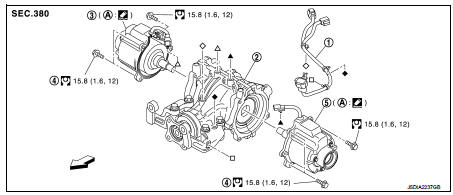
1. Sub-harness
2. Rear final drive assembly
3. Electric controlled coupling (right)
4. Reamer bolt
5. Electric controlled coupling (left)
A. Gear carrier mouting face
 : Vehicle front
 : N·m (kg-m, ft-lb)
 : Apply Genuine Liquid Gasket 1217
or equivalent.
Removal and Installation
REMOVAL
1. Remove rear drive shaft. Refer to RAX-17, "Removal and Installation".
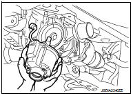
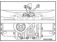
2. Disconnect electric controlled coupling connector (1) from subharness (2).
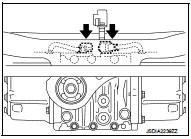
3. Remove connector clip ( ) from
final drive assembly.
4. Remove electric controlled coupling from final drive assembly.
5. Remove sub-harness from final drive assembly.
CAUTION:
Remove sub-harness only when necessary.
INSTALLATION
1. Install new sub-harness clip to sub-harness.
CAUTION:
• Check original mounting dimensions to install clip to the original position.
• Baffle pin must be functioning normally.
2. Install sub-harness to final drive assembly.
CAUTION:
Check the area around the rotating object to see that there is no interference.
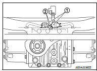
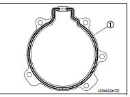
3. Apply liquid gasket (1) to mating surface of coupling cover.
CAUTION:
• Remove old gasket adhering to the mounting surfaces.
Also remove any moisture, oil, or foreign material adhering to the mounting surfaces.
• Overlap both ends of the bead for at least 3 mm (0.12 in).
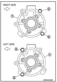
4. Install electric controlled coupling (1) to spline of stem center with grommet of harness facing upward, temporarily tighten reamer bolts (2) to the positions shown in the figure.
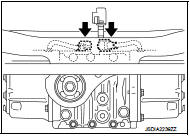
5. Tighten reamer bolts and coupling cover mounting bolts to the specified torque.
 : Vehicle front
CAUTION:
Never allow harness to get caught in the bolt.
6. Install the new connector clip (
) to final drive assembly.
CAUTION:
Never reuse connector clip.
7. Connect electric controlled coupling connector (1) to sub-harness (2).
8. Install rear drive shaft. Refer to RAX-17, "Removal and Installation".
9. When oil leaks while removing, check oil level after the installation.
Refer to DLN-132, "Inspection".
10. When replacing electric controlled coupling, perform writing unit parameter. Refer to DLN-39, "Work Procedure".
 Side oil seal
Exploded View
1. Rear final drive assembly
2. Side oil seal (right)
3. Electric controlled coupling (right)
4. Reamer bolt
5. Side oil seal (left)
6. Electric controlled coupling (left)
A ...
 Electric controlled coupling oil seal
Exploded View
1. Rear final drive assembly
2. Electric controlled coupling oil seal
A. Oil seal lip
: Vehicle front
: Always replace after every
disassembly.
: Apply multi purpose grease
: ...
Other materials:
Main power supply and ground circuit
Diagnosis Procedure
1.CHECK TCM POWER CIRCUIT 1
1. Turn the ignition switch OFF.
2. Disconnect the TCM connector.
3. Check the voltage between the TCM harness connector terminals and ground.
Is the inspection result normal?
YES >> GO TO 2.
NO >> GO TO 4.
2.CHECK TCM POWER C ...
Ecu diagnosis information
BCM (body control module)
Reference Value
VALUES ON THE DIAGNOSIS TOOL
TERMINAL LAYOUT
PHYSICAL VALUES
NOTE:
• *1: Without automatic A/C
• *2: RHD models
• *3: With manual A/C
• *4: LHD models
Fail-safe
FAIL-SAFE CONTROL BY DTC
BCM performs fail-sa ...
Back door
Exploded View
REMOVAL
1. Back door weather-strip
2. Back door stay
3. Back door stay lower bracket
4. Bumper rubber
5. Back door striker
6. Back door panel
7. Back door hinge
8. Hole cover
A : Center mark
B : Seam
: Do not reuse
: Body grea
Back door assembly
BACK DOOR ASSEMBLY ...
