Nissan Juke Service and Repair Manual : Electric controlled coupling oil seal
Exploded View
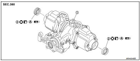
1. Rear final drive assembly 2. Electric controlled coupling oil seal
A. Oil seal lip
 : Vehicle front
 : Always replace after every
disassembly.
 : Apply multi purpose grease
 : Apply gear oil.
Removal and Installation
REMOVAL
1. Remove rear drive shafts. Refer to RAX-17, "Removal and Installation".
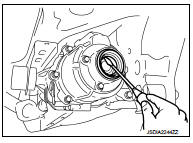
2. Remove electric controlled coupling oil seals from electric controlled coupling, using a suitable tool.
CAUTION:
Never damage electric controlled coupling.
INSTALLATION
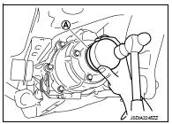
1. Install electric controlled coupling oil seals to electric controlled coupling, using the drift (A) (SST: KV38109700).
NOTE
:
The use of the special service tool satisfies the mounting dimensions.
CAUTION:
• Never reuse oil seals.
• When installing, never incline oil seals.
• Apply multi-purpose grease onto oil seal lips, and gear oil onto the circumference of oil seal.
2. Install rear drive shafts. Refer to RAX-17, "Removal and Installation".
3. When oil leaks while removing, check oil level after the installation. Refer to DLN-132, "Inspection".
 Electric controlled coupling
Exploded View
1. Sub-harness
2. Rear final drive assembly
3. Electric controlled coupling (right)
4. Reamer bolt
5. Electric controlled coupling (left)
A. Gear carrier mouting face
: Vehic ...
 Unit removal and installation
REAR FINAL DRIVE ASSEMBLY ...
Other materials:
P0117, P0118 ECT sensor
DTC Logic
DTC DETECTION LOGIC
DTC CONFIRMATION PROCEDURE
1.PRECONDITIONING
If DTC Confirmation Procedure has been previously conducted, always perform
the following procedure
before conducting the next test.
1. Turn ignition switch OFF and wait at least 10 seconds.
2. Turn ignition swit ...
Hazard switch
Exploded View
1. Instrument panel assembly
2. Hazard switch
: Pawl
Removal and Installation
REMOVAL
1. Remove Audio unit. Refer to AV-38, "Removal and Installation".
2. Disengage fixing pawls, and then remove hazard switch from instrument panel
inside to outside.
INSTALLATIO ...
NISSAN Vehicle Immobilizer System
The NISSAN Vehicle Immobilizer System is a sophisticated anti-theft security feature designed specifically for your Nissan Leaf. It ensures that the EV power switch cannot be shifted into the READY to drive position unless the vehicle detects an authentic, registered Intelligent Key.
...
