Nissan Juke Service and Repair Manual : RHD
RHD : Wiring Diagram
For connector terminal arrangements, harness layouts, and alphabets in a
 (option abbreviation; if not
described in wiring diagram), refer to GI-12, "Connector Information/Explanation
of Option Abbreviation".
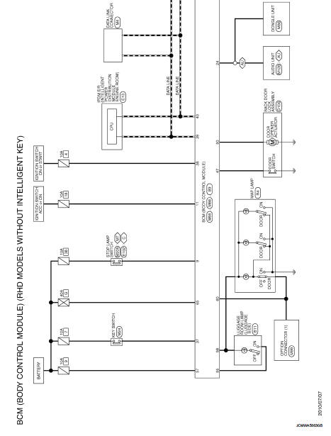
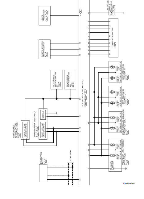
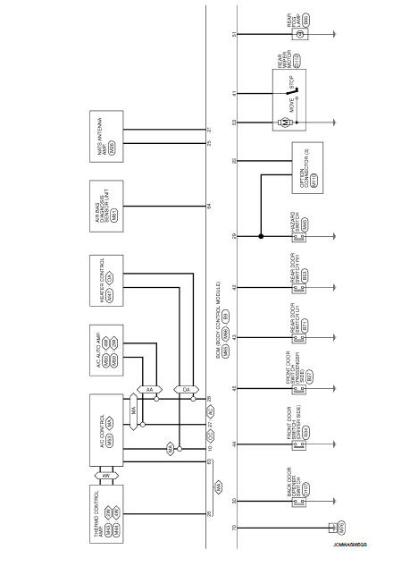

 BCM
BCM
LHD
LHD : Wiring Diagram
For connector terminal arrangements, harness layouts, and alphabets in a
(option abbreviation; if not
described in wiring diagram), refer to GI-12, "Connector Inform ...
 Basic inspection
...
Other materials:
B2602 shift position
DTC Logic
DTC DETECTION LOGIC
NOTE:
• If DTC B2602 is displayed with DTC U1000, first perform the trouble diagnosis
for DTC U1000. Refer to
BCS-83, "DTC Logic".
• If DTC B2602 is displayed with DTC U1010, first perform the trouble diagnosis
for DTC U1010. Refer to
BCS-84, &qu ...
B260C steering lock unit
DTC Logic
DTC DETECTION LOGIC
DTC CONFIRMATION PROCEDURE
1.PERFORM DTC CONFIRMATION PROCEDURE
1. Shift selector lever to the P position.
2. Press push-button ignition switch under the following condition.
- Brake pedal: Not depressed
3. Turn ignition switch ON.
4. Turn ignition switch OFF. ...
Wiring diagram
MANUAL AIR CONDITIONING SYSTEM
Wiring Diagram
For connector terminal arrangements, harness layouts, and alphabets in a
(option abbreviation; if not
described in wiring diagram), refer to GI-12, "Connector Information/Explanation
of Option Abbreviation".
...
