Nissan Juke Service and Repair Manual : Power supply and ground circuit
Diagnosis Procedure
1.CHECK GROUND CONNECTION
1. Turn ignition switch OFF.
2. Check ground connection E21 and E38. Refer to Ground Inspection in GI-44, "Circuit Inspection".
Is the inspection result normal? YES >> GO TO 2.
NO >> Repair or replace ground connection.
2.CHECK ECM GROUND CIRCUIT FOR OPEN AND SHORT
1. Disconnect ECM harness connectors.
2. Check the continuity between ECM harness connector and ground.
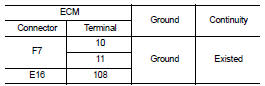
3. Also check harness for short to power.
Is the inspection result normal? YES >> GO TO 4.
NO >> GO TO 3.
3.DETECT MALFUNCTIONING PART
Check the following.
ŌĆó Harness connectors E8, F1 ŌĆó Harness for open or short between ECM and ground
>> Repair open circuit or short to power in harness or connectors.
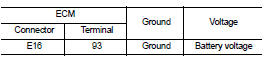
4.CHECK ECM POWER SUPPLY CIRCUIT-I
1. Reconnect ECM harness connectors.
2. Turn ignition switch ON.
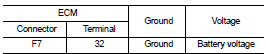
3. Check the voltage between ECM harness connector and ground.
Is the inspection result normal? YES >> GO TO 6.
NO >> GO TO 5.
5.DETECT MALFUNCTIONING PART
Check the following.
ŌĆó 15 A fuse (No. 62)
ŌĆó Harness for open or short between ECM and fuse
>> Repair open circuit or short to ground or short to power in harness or connectors.
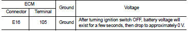
6.CHECK ECM POWER SUPPLY CIRCUIT-II
1. Turn ignition switch OFF and wait at least 10 seconds.
2. Turn ignition switch ON and then OFF.
Check the voltage between ECM harness connector and ground.
Is the inspection result normal? YES >> GO TO 7.
NO >> GO TO 9.
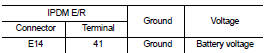
7.CHECK ECM POWER SUPPLY CIRCUIT-III
1. Turn ignition switch ON.
2. Check the voltage between IPDM E/R harness connector and ground.
Is the inspection result normal? YES >> GO TO 8.
NO >> Replace IPDM E/R.
8.CHECK INTERMITTENT INCIDENT
Refer to GI-42, "Intermittent Incident".
>> INSPECTION END
9.CHECK ECM POWER SUPPLY CIRCUIT-IV
1. Turn ignition switch OFF and wait at least 10 seconds.
2. Check the voltage between ECM harness connector and ground.
Is the inspection result normal? YES >> GO TO 13.
NO >> GO TO 10.
10.CHECK ECM POWER SUPPLY CIRCUIT-V
1. Disconnect ECM harness connector.
2. Disconnect IPDM E/R harness connector E14.
3. Check the continuity between ECM harness connector and IPDM E/R harness connector.
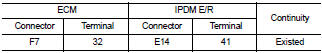
4. Also check harness for short to ground and short to power.
Is the inspection result normal? YES >> GO TO 12.
NO >> GO TO 11.
11.DETECT MALFUNCTIONING PART
Check the following.
ŌĆó Harness connectors E8, F1 ŌĆó Harness for open or short between ECM and IPDM E/R
>> Repair open circuit or short to ground or short to power in harness or connectors.
12.CHECK 20 A FUSE
1. Disconnect 20 A fuse (No. 43) from IPDM E/R.
2. Check 20 A fuse.
Is the inspection result normal? YES >> GO TO 14.
NO >> Replace 20 A fuse.
13.CHECK ECM POWER SUPPLY CIRCUIT-VI
1. Disconnect ECM harness connector.
2. Disconnect IPDM E/R harness connector E14.
3. Check the continuity between ECM harness connector and IPDM E/R harness connector.
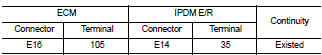
4. Also check harness for short to ground and short to power.
Is the inspection result normal? YES >> GO TO 14.
NO >> Repair open circuit or short to ground or short power in harness or connectors.
14.CHECK INTERMITTENT INCIDENT
Refer to GI-42, "Intermittent Incident".
Is the inspection result normal? YES >> Replace IPDM E/R.
NO >> Repair or replace harness or connectors.
 Trouble diagnosis - specification valuE
Description
The specification (SP) value indicates the tolerance of the value that is
displayed in ŌĆ£SPECŌĆØ of ŌĆ£DATA MONITORŌĆØ
mode of CONSULT-III during normal operation of the Engine Contro ...
 U1000, U1001 CAN COMM CIRCUIT
Description
CAN (Controller Area Network) is a serial communication line for real time
application. It is an on-vehicle multiplex
communication line with high data communication speed and excellen ...
Other materials:
Tire dressing
NISSAN does not recommend the use of tire dressings. Tire manufacturers apply
a coating to the tires to help reduce discoloration of the rubber. If a tire dressing
is applied to the tires, it may react with the coating and form a compound.
This compound may come off the tire while driving and s ...
Diagnosis Procedure
WARNING:
ŌĆó Before servicing, turn ignition switch OFF, disconnect battery negative
terminal and wait at least 3
minutes. (To discharge backup capacitor.)
ŌĆó Never use unspecified tester or other measuring device.
1.CHECK HARNESS CONNECTOR
Check the harness connector.
Is the inspection ...
Removal and installation
POWER WINDOW MAIN SWITCH
Removal and Installation
REMOVAL
1. Remove power window main switch finisher. Refer to INT-13, "Removal and
Installation".
2. Remove power window main switch (1) from power window
main switch finisher (2) using flat-head screw driver (A).
: Pawl
CAUTION:
...
