Nissan Juke Service and Repair Manual : Power supply and ground circuit
Diagnosis Procedure
1.CHECK ABS ACTUATOR AND ELECTRIC UNIT (CONTROL UNIT) IGNITION POWER SUPPLY
1. Turn the ignition switch OFF.
2. Disconnect ABS actuator and electric unit (control unit) harness connector.
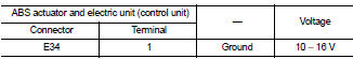
3. Check voltage between ABS actuator and electric unit (control unit) harness connector and ground.
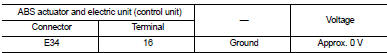
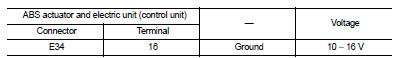
4. Turn the ignition switch ON
CAUTION:
Never start engine
.
5. Check voltage between ABS actuator and electric unit (control unit) harness connector and ground.
Is the inspection result normal? YES >> GO TO 3.
NO >> GO TO 2.
2.CHECK ABS ACTUATOR AND ELECTRIC UNIT (CONTROL UNIT) IGNITION POWER SUPPLY CIRCUIT
1. Turn the ignition switch OFF.
2. Check 10 A fuse (#57).
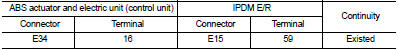
3. Disconnect IPDM E/R harness connector.
4. Check continuity between ABS actuator and electric unit (control unit) harness connector and IPDM E/R harness connector.
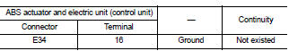
5. Check for continuity between ABS actuator and electric unit (control unit) harness connector and the ground.
Is the inspection result normal? YES >> Perform trouble diagnosis for ignition power supply. Refer to PG-15, "Wiring Diagram - IGNITION POWER SUPPLY -".
NO >> Repair or replace error-detected parts.
3.CHECK MOTOR AND MOTOR RELAY POWER SUPPLY
1. Turn the ignition switch OFF.
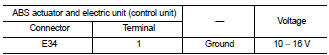
2. Check voltage between ABS actuator and electric unit (control unit) harness connector and ground.
3. Turn the ignition switch ON.
CAUTION:
Never start engine.
4. Check voltage between ABS actuator and electric unit (control unit) harness connector and ground.
Is the inspection result normal? YES >> GO TO 5.
NO >> GO TO 4.
4.CHECK MOTOR AND MOTOR RELAY POWER SUPPLY CIRCUIT
1. Turn the ignition switch OFF.
2. Check 30 A fusible link (K).
3. Check continuity and short circuit between ABS actuator and electric unit (control unit) harness connector terminal (1) and 30 A fusible link (K).
Is the inspection result normal? YES >> Perform trouble diagnosis for battery power supply. Refer to PG-10, "Wiring Diagram - BATTERY POWER SUPPLY -".
NO >> Repair or replace error-detected parts.
5.CHECK ACTUATOR RELAY, ABS IN VALVE, ABS OUT VALVE POWER SUPPLY
1. Turn the ignition switch OFF.
2. Check voltage between ABS actuator and electric unit (control unit) harness connector and ground.
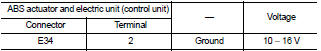
3. Turn the ignition switch ON
CAUTION:
Never start engine.
4. Check voltage between ABS actuator and electric unit (control unit) harness connector and ground.
Is the inspection result normal? YES >> GO TO 7.
NO >> GO TO 6.
6.CHECK ACTUATOR RELAY, ABS IN VALVE, ABS OUT VALVE POWER SUPPLY CIRCUIT
1. Turn the ignition switch OFF.
2. Check 40 A fusible link (F).
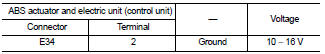
3. Check continuity and short circuit between ABS actuator and electric unit (control unit) harness connector terminal (2) and 40 A fusible link (F).
Is the inspection result normal? YES >> Perform trouble diagnosis for battery power supply. Refer to PG-10, "Wiring Diagram - BATTERY POWER SUPPLY -".
NO >> Repair or replace error-detected parts.
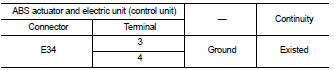
7.CHECK ABS ACTUATOR AND ELECTRIC UNIT (CONTROL UNIT) GROUND CIRCUIT
Check for continuity between ABS actuator and electric unit (control unit) harness connector and the ground.
Is the inspection result normal? YES >> GO TO 8.
NO >> Repair or replace error-detected parts.
8.CHECK TERMINAL
• Check ABS actuator and electric unit (control unit) pin terminals for damage or loose connection with harness connector.
• Check IPDM E/R pin terminals for damage or loose connection with harness connector.
Is the inspection result normal? YES >> INSPECTION END
NO >> Repair or replace error-detected parts.
 U1010 control unit (can)
Description
CAN (Controller Area Network) is a serial communication line for real time
application. It is an on-vehicle multiplex
communication line with high data communication speed and excellen ...
 Stop lamp switch
Component Function Check
1.CHECK STOP LAMP SWITCH OPERATION
Depress brake pedal and check that stop lamp turns ON, or release brake pedal
and check stop lamp turns
OFF.
Is the inspection resul ...
Other materials:
Component parts
Component Parts Location
1. Back door lock assembly
2. Front door lock assembly (driver
side)
3. Front door switch (driver side)
4. Power window main switch
(door lock/unlock switch)
5. Key switch
6. Combination meter
7. Door lock status indicator
8. Remote keyless entry receiver
9. ...
Mainshaft and gear
Exploded View
1. Mainshaft front bearing outer
race
2. Mainshaft front bearing inner race
3. Mainshaft
4. 1st main gear
5. 1st inner baulk ring
6. 1st synchronizer cone
7. 1st outer baulk ring
8. 1st-2nd coupling sleeve
9. Insert key
10. 1st-2nd synchronizer hub
11. 2nd outer baulk ...
Checking engine coolant level
Check the coolant level in the reservoir when the engine is cold. If the coolant
level is below the MIN level 2 , open the reservoir cap and add coolant up to the
MAX level 1 . If the reservoir is empty, check the coolant level in the radiator
when the engine is cold. If there is insufficien ...
