Nissan Juke Service and Repair Manual : U1010 control unit (can)
Description
CAN (Controller Area Network) is a serial communication line for real time application. It is an on-vehicle multiplex communication line with high data communication speed and excellent error detection ability. Many electronic control units are equipped onto a vehicle, and each control unit shares information and links with other control units during operation (not independent). In CAN communication, control units are connected with 2 communication lines (CAN-H line, CAN-L line) allowing a high rate of information transmission with less wiring.
Each control unit transmits/receives data but selectively reads required data only.
DTC Logic
DTC DETECTION LOGIC
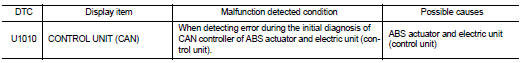
DTC CONFIRMATION PROCEDURE
1.PRECONDITIONING
If ‚ÄúDTC CONFIRMATION PROCEDURE‚ÄĚ has been previously conducted, always turn ignition switch OFF and wait at least 10 seconds before conducting the next test.
>> GO TO 2.
2.CHECK DTC DETECTION
 With CONSULT-III
1. Turn the ignition switch OFF to ON.
2. Perform self-diagnosis for ‚ÄúABS‚ÄĚ.
Is DTC ‚ÄúU1010‚ÄĚ detected? YES >> Proceed to BRC-63, "Diagnosis Procedure".
NO >> INSPECTION END
Diagnosis Procedure
1.CHECK ABS ACTUATOR AND ELECTRIC UNIT (CONTROL UNIT)
Check ABS actuator and electric unit (control unit) harness connector for disconnection and deformation.
Is the inspection result normal? YES >> Replace ABS actuator and electric unit (control unit). Refer to BRC-90, "Removal and Installation".
NO >> Repair or replace error-detected parts.
 U1000 can comm circuit
Description
CAN (Controller Area Network) is a serial communication line for real time
application. It is an on-vehicle multiplex
communication line with high data communication speed and excellen ...
 Power supply and ground circuit
Diagnosis Procedure
1.CHECK ABS ACTUATOR AND ELECTRIC UNIT (CONTROL UNIT) IGNITION POWER
SUPPLY
1. Turn the ignition switch OFF.
2. Disconnect ABS actuator and electric unit (control unit) harnes ...
Other materials:
Component parts
Charging system
CHARGING SYSTEM : Component Parts Location
1. Charge warning lamp (On the combination
meter)
2. Alternat
CHARGING SYSTEM : Component Description
Power generation voltage variable control system
POWER GENERATION VOLTAGE VARIABLE CONTROL SYSTEM : Component
Parts Location
N ...
P1726 throttle control signal
Description
Electric throttle control actuator consists of throttle control motor,
accelerator pedal position sensor, throttle
position sensor etc. The actuator sends a signal to the ECM, and ECM sends the
signal to TCM with CAN
communication.
DTC Logic
DTC DETECTION LOGIC
DTC CONFIRMATI ...
Heated steering wheel switch
The Nissan Leaf heated steering wheel system is designed with intelligent efficiency, operating only when the surface temperature of the steering wheel is below approximately 68¬ļF (20¬ļC).
To activate the system, push the heated steering wheel switch while the p ...
