Nissan Juke Service and Repair Manual : Periodic maintenance
REAR PROPELLER SHAFT
Inspection
APPEARANCE AND NOISE
• Check the propeller shaft tube surface for dents or cracks. If damaged, replace propeller shaft assembly.
• If center bearing is noisy or damaged, replace propeller shaft assembly.
VIBRATION
If vibration is present at high speed, inspect propeller shaft runout first.
1. With a dial indicator, measure propeller shaft runout at runout measuring points by rotating final drive companion flange with hands.
Propeller shaft runout : Refer to DLN-125, "Propeller Shaft Runout".
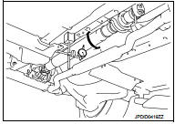
• Propeller shaft runout measuring point (Point “
”)
 : Front
Dimension A: 542 mm (21.34 in) B: 516.5 mm (20.33 in)
2. If runout still exceeds specifications, separate propeller shaft at final drive companion flange or transfer companion flange; then change the phase between companion flange and propeller shaft by the one bolt hole at a time and install propeller shaft.
3. Check runout again. If runout still exceeds specifications, replace propeller shaft assembly.
4. Check the vibration by driving vehicle.
 Symptom diagnosis
NOISE, VIBRATION AND HARSHNESS (NVH) TROUBLESHOOTING
NVH Troubleshooting Chart
Use the chart below to find the cause of the symptom. If necessary, repair or
replace these parts.
×: Applic ...
 Removal and installation
REAR PROPELLER SHAFT ...
Other materials:
Seat belt buckle switch signal circuit (driver side)
Component Function Check
1.CHECK COMBINATION METER INPUT SIGNAL
Select the “Data Monitor” for the “METER/M&A” and check the “BUCKLE SW”
monitor value.
BUCKLE SW
When driver seat belt is fastened : Off
When driver seat belt is unfastened : On
>> INSPECTION END
Diagnosis ...
Wheel sensor
Front wheel sensor : Exploded View
1. Front LH wheel sensor
2. Front LH wheel sensor harness connector
: Vehicle front
: N·m (kg-m, in-lb)
NOTE:
Front RH wheel sensor is symmetrically opposite of LH.
Front wheel sensor : Removal and Installat
REMOVAL
1. Remove tires.
2. Remove the fend ...
On Board Diagnostic (OBD) System of Engine
The ECM has an on board diagnostic system. It will light up the malfunction
indicator (MI) to warn the driver of
a malfunction causing emission deterioration.
CAUTION:
• Be sure to turn the ignition switch OFF and disconnect the battery negative
cable before any repair
or inspection work ...
