Nissan Juke Service and Repair Manual : P183E yaw rate sensor
DTC Logic
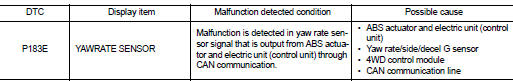
DTC DETECTION LOGIC
DTC CONFIRMATION PROCEDURE
1.PRECONDITIONING
If “DTC CONFIRMATION PROCEDURE” has been previously conducted, always turn ignition switch OFF and wait at least 10 seconds before conducting the next test.
>> GO TO 2.
2.DTC REPRODUCTION PROCEDURE
 With CONSULT-III
1. Start the engine and drive at 30 km/h (19 MPH) or more for approximately 1minute.
2. Perform self-diagnosis for “ALL MODE AWD/4WD”.
Is DTC “P183E” detected? YES >> Proceed to diagnosis procedure. Refer to DLN-71, "Diagnosis Procedure".
NO >> INSPECTION END
Diagnosis Procedure
1.PERFORM ABS ACTUATOR AND ELECTRIC UNIT (CONTROL UNIT) SELF-DIAGNOSIS
With CONSULT-III
Perform self-diagnosis for “ABS”.
Is any DTCs detected? YES >> Check the DTCs. Refer to BRC-142, "DTC Index".
NO >> GO TO 2.
2.ERASE SELF-DIAGNOSTIC RESULT
With CONSULT-III
1. Erase self-diagnostic results for “ALL MODE AWD/4WD”.
2. Start the engine and drive vehicle at 30 km/h (19 MPH) or more.
3. Check that ABS warning lamp turns OFF.
Does ABS warning lamp turn OFF? YES >> GO TO 3.
NO >> Refer to BRC-212, "Diagnosis Procedure".
3.CHECK TERMINALS AND HARNESS CONNECTORS
Check 4WD control module pin terminals for damage or loose connection with harness connector.
Is inspection result normal? YES >> After turning the ignition switch OFF, perform DTC confirmation procedure again. When DTC “P183E” is detected, Replace 4WD control module. Refer to DLN-91, "Removal and Installation".
NO >> Repair or replace error-detected parts.
 P183D side G sensor
DTC Logic
DTC DETECTION LOGIC
DTC CONFIRMATION PROCEDURE
1.PRECONDITIONING
If “DTC CONFIRMATION PROCEDURE” has been previously conducted, always turn
ignition switch OFF and
wait at least ...
 P183F gear position signal
DTC Logic
DTC DETECTION LOGIC
DTC CONFIRMATION PROCEDURE
1.PRECONDITIONING
If “DTC CONFIRMATION PROCEDURE” has been previously conducted, always turn
ignition switch OFF and
wait at least ...
Other materials:
Line pressure test
Work Procedure
INSPECTION
1. Check the engine oil level. Replenish if necessary. LU-25, "Inspection".
2. Check for leak of the CVT fluid. Refer to TM-480, "Inspection".
3. Drive for about 10 minutes to warm up the vehicle so that the CVT fluid
temperature is 50 to 80°C (12 ...
Service data and specifications (SDS)
Wheel Bearing
Drive Shaft
M/T
*: For measuring position, refer to FAX-54, "WHEEL SIDE : Disassembly and
Assembly" (Wheel side), FAX-
56, "TRANSAXLE SIDE : Disassembly and Assembly" (Transaxle side).
CVT
*: For measuring position, refer to FAX-54, "WHEEL SIDE ...
Driver side power window does not operate
Diagnosis Procedure
1.CHECK FRONT POWER WINDOW MOTOR (DRIVER SIDE)
Check front power window motor (driver side).
Refer to PWC-26, "DRIVER SIDE : Component Function Check".
Is the inspection result normal?
YES >> GO TO 2.
NO >> Repair or replace the malfunctioning pa ...
