Nissan Juke Service and Repair Manual : Service data and specifications (SDS)
Wheel Bearing

Drive Shaft
M/T
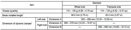
*: For measuring position, refer to FAX-54, "WHEEL SIDE : Disassembly and Assembly" (Wheel side), FAX- 56, "TRANSAXLE SIDE : Disassembly and Assembly" (Transaxle side).
CVT
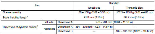
*: For measuring position, refer to FAX-54, "WHEEL SIDE : Disassembly and Assembly" (Wheel side), FAX- 56, "TRANSAXLE SIDE : Disassembly and Assembly" (Transaxle side).
 Front drive shaft
Exploded View
LEFT SIDE
1. Circular clip
2. Dust shield
3. Housing assembly
4. Boot band
5. Boot
6. Damper band
7. Dynamic damper
8. Circular clip
9. Joint sub-assembly
: Wheel side ...
 Front Axle K9K
...
Other materials:
P0746 pressure control solenoid A
Description
The line pressure solenoid valve regulates the oil pump discharge pressure to
suit the driving condition in
response to a signal sent from the TCM.
DTC Logic
DTC DETECTION LOGIC
DTC CONFIRMATION PROCEDURE
CAUTION:
Always drive vehicle at a safe speed.
NOTE:
If “DTC CONFIRM ...
Intelligent key warning buzzer
Component Function Check
1.CHECK FUNCTION
1. Select “INTELLIGENT KEY” of “BCM” using CONSULT-III.
2. Select “OUTSIDE BUZZER” in “ACTIVE TEST” mode.
3. Check that the function operates normally according to the following
conditions.
Is the inspection result normal?
YES >& ...
P1832 TCS operation signal
DTC Logic
DTC DETECTION LOGIC
DTC CONFIRMATION PROCEDURE
1.DTC REPRODUCTION PROCEDURE
With CONSULT-III
1. Start the engine and drive at 30 km/h (19 MPH) or more.
2. Perform self-diagnosis for “ALL MODE AWD/4WD”.
Is DTC “P1832” detected?
YES >> Proceed to diagnosis procedure ...
