Nissan Juke Service and Repair Manual : Front drive shaft
Exploded View
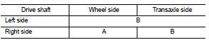
LEFT SIDE
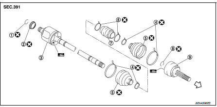
1. Circular clip
2. Dust shield
3. Housing assembly
4. Boot band
5. Boot
6. Damper band
7. Dynamic damper
8. Circular clip
9. Joint sub-assembly
 : Wheel side
 : Fill NISSAN Genuine grease or
equivalent.
 : Always replace after every
disassembly.
RIGHT SIDE
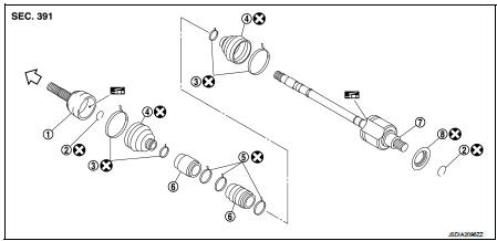
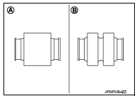
1. Joint sub-assembly 2. Circular clip 3. Boot band 4. Boot 5. Band 6. Dynamic damper 7. Housing assembly 8. Dust shield
: Wheel side
: Fill NISSAN Genuine grease or
equivalent.
: Always replace after every
disassembly.
Removal and Installation
REMOVAL
1. Remove tires. Refer to WT-7, "Removal and Installation".
2. Remove wheel sensor and sensor harness. Refer to BRC-84, "FRONT WHEEL SENSOR : Exploded View" (Without ESP) or BRC-224, "FRONT WHEEL SENSOR : Exploded View" (With ESP).
3. Remove lock plate from strut assembly. Refer to FSU-10, "Removal and Installation".
4. Remove caliper assembly. Hang caliper assembly not to interfere with work. Refer to BR-57, "BRAKE CALIPER ASSEMBLY : Removal and Installation" (LHD) or BR-123, "BRAKE CALIPER ASSEMBLY : Removal and Installation" (RHD).
CAUTION:
Never depress brake pedal while brake caliper is remove
d.
5. Remove disc rotor. Refer to FAX-43, "Removal and Installation".
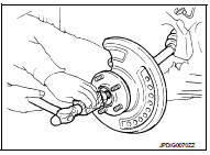
6. Remove cotter pin, and then loosen wheel hub lock nut. Refer to FAX-43, "Removal and Installation".
7. Patch wheel hub lock nut with a piece of wood. Hammer the wood to disengage wheel hub assembly from drive shaft.
NOTE
:
Use suitable puller, if wheel hub assembly and drive shaft cannot
be separated even after performing the above procedure.
8. Remove wheel hub lock nut. Refer to FAX-43, "Removal and Installation".
9. Remove transverse link from steering knuckle. Refer to FAX-43, "Removal and Installation".
10. Remove shaft assembly from wheel hub assembly.
CAUTION:
• Never place drive shaft joint at an extreme angle. Also be
careful not to overextend slide joint.
• Never allow drive shaft to hang down without support for joint sub-assembly, shaft and the other parts.
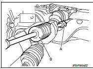
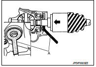
11. Use the drive shaft attachment (A) (SST: KV40107500) and a sliding hammer (B) (commercial service tool) while inserting tip of the drive shaft attachment between shaft and transaxle assembly, and then remove drive shaft from transaxle assembly.
CAUTION:
• Never place drive shaft joint at an extreme angle when
removing drive shaft. Also be careful not to overextend
slide joint.
• Confirm that the circular clip is attached to the drive shaft
.
12. Perform inspection after removal. Refer to FAX-59, "Inspection".
INSTALLATION
Note the following, and install in the reverse order of removal.
Transaxle Side
• Always replace differential side oil seal with new one when installing drive
shaft. Refer to TM-23, "Removal
and Installation" (5M/T) or TM-498, "Removal and Installation" (CVT).
• Place the protector (A) (SST: KV38107900) onto transaxle assembly to prevent damage to the oil seal while inserting drive shaft.
Slide drive shaft sliding joint and tap with a hammer to install securely.
CAUTION:
Check that circular clip is completely engaged.
• Perform inspection after removal. Refer to FAX-59, "Inspection".
Wheel Hub Side
• Clean the matching surface of wheel hub lock nut and wheel hub assembly.
CAUTION:
Never apply lubricating oil to these matching surface.
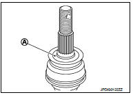
• Clean the matching surface of drive shaft and wheel hub assembly.
And then apply paste [service parts (440037S000)] to surface (A) of joint sub-assembly of drive shaft.
CAUTION:
Apply paste to cover entire flat surface of joint sub-assembly
of drive shaft.
Amount paste : 1.0 – 3.0 g (0.04 – 0.10 oz)
• Use the following torque range for tightening the wheel hub lock nut.
 : 180 – 185 N·m (18.4 – 18.8
kg-m, 133 – 136 ft-lb)
CAUTION:
• Since the drive shaft is assembled by press-fitting, use the tightening torque
range for the wheel
hub lock nut.
• Be sure to use torque wrench to tighten the wheel hub lock nut. Never use a power tool.
• Never reuse wheel hub lock nut.
NOTE:
Wheel hub lock nut tightening torque does not over torque for avoiding axle noise, and does not less than torque for avoiding looseness.
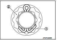
• Align the matching marks that have been made during removal when reusing the disc rotor.
• When installing a cotter pin (1) and adjusting cap (2), securely bend the basal portion to prevent rattles.
CAUTION:
Never reuse cotter pin.
• Perform the final tightening of each of parts under unladen conditions, which were removed when removing wheel hub assembly and axle housing.
• Perform inspection after installation. Refer to FAX-59, "Inspection".
Wheel side : Disassembly and Assembly
DISASSEMBLY
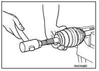
1. Fix shaft with a vise.
CAUTION:
Protect shaft when fixing with a vise using aluminum or copper plates.
2. Remove boot bands, and then remove boot from joint sub-assembly.
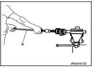
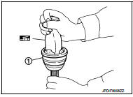
3. Screw drive shaft puller (A) (commercial service tool) into joint sub-assembly screw part to a length of 30 mm (1.18 in) or more.
Support drive shaft with one hand and pull out joint sub-assembly from shaft.
CAUTION:
• Align drive shaft puller and drive shaft and remove them
by pulling firmly and uniformly.
• If joint sub-assembly cannot be removed after five or more unsuccessful attempts, replace shaft and joint sub assembly as a set.
4. Remove circular clip from shaft.
5. Remove boot from shaft.
6. Perform inspection after disassembly. Refer to FAX-59, "Inspection".
ASSEMBLY
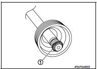
1. Clean the old grease on joint sub-assembly with paper waste.
2. Fill serration slot joint sub-assembly (1) with NISSAN genuine grease or equivalent until the serration slot and ball groove become full to the brim.
CAUTION:
After applying grease, use a paper waste to wipe off old
grease that has oozed out.
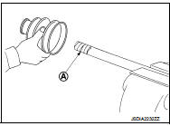
3. Install boot and boot bands to shaft.
CAUTION:
• Wrap serration on shaft with tape (A) to protect the boot
from damage.
• Never reuse boot and boot band.
4. Remove the tape wrapped around the serration on shaft.
5. Position the circular clip (1) on groove at the shaft edge.
CAUTION:
Never reuse circular clip.
NOTE:
Drive joint inserter is recommended when installing circular clip.
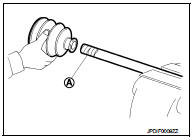
6. Align both center axles of the shaft edge and joint sub-assembly.
Then assemble shaft with joint sub-assembly holding circular clip.
7. Install joint sub-assembly to shaft using plastic hammer.
CAUTION:
• Check circular clip is properly positioned on groove of the
joint sub-assembly.
• Confirm that joint sub-assembly is correctly engaged while rotating drive shaft.
8. Apply the specified amount of grease into the boot inside from large diameter side of boot.
Grease amount : Refer to FAX-60, "Drive Shaft".
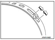
9. Install the boot securely into grooves (indicated by “*” marks) shown in the figure.
CAUTION:
If grease adheres to the boot mounting surface (indicated
by “*” marks) on the shaft or joint sub-assembly, boot may
be removed. Remove all grease from the boot mounting
surface.
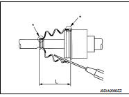
10. To prevent the deformation of the boot, adjust the boot installation length (L) to the specified value shown below by inserting the suitable tool into inside of the boot from the large diameter side of the boot and discharging the inside air.
L : Refer to FAX-60, "Drive Shaft".
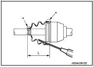
CAUTION:
• If the boot installation length exceeds the standard, it may cause breakage of
the boot.
• Be careful not to touch the inside of the boot with a tip of tool.
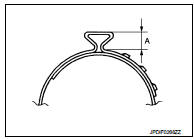
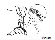
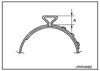
11. Secure the large and small ends of the boot with boot bands using the boot band crimping tool (A) (SST: KV40107300).
CAUTION: • Never reuse boot band.
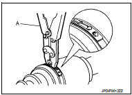
• Secure boot band so that dimension (A) meets the specification as shown in the figure.
A : 5.0 mm (0.197 in) or less.
12. Check that displacement does not occur when boot is rotated with the joint sub-assembly and shaft fixed.
CAUTION:
• Reinstall them using boot bands when boot installation
positions become incorrect.
• Never reuse boot band.
Transaxle side : Disassembly and Assembly
DISASSEMBLY
1. Fix shaft with a vise.
CAUTION:
Protect shaft using aluminum or copper plates when fixing with a vise.
2. Remove wheel side boot. Refer to FAX-48, "WHEEL SIDE : Removal and Installation".
3. Remove dynamic damper as per the following instructions: a. Remove boot band.
b. Remove dynamic damper from housing assembly.
4. Remove boot bands, then remove boot from housing assembly.
5. Remove circular clip from housing assembly.
6. Remove dust shield from housing assembly.
7. Perform inspection after disassembly. Refer to FAX-59, "Inspection".
ASSEMBLY
1. Clean the old grease on housing assembly with paper waste.
2. Install boot and boot bands to housing assembly.
CAUTION:
• Wrap serration on housing assembly with tape (A) to protect
the boot from damage.
• Never reuse boot and boot band.
3. Remove the tape wrapped around the serration on housing assembly.
4. Apply NISSAN genuine grease (refer to parts catalog) to housing assembly.
Grease amount : Refer to FAX-60, "Drive Shaft".
5. Install boot securely into grooves (indicated by “*” marks) shown in the figure.
CAUTION:
If grease adheres to the boot mounting surface (with “*”
marks) on shaft or housing, boot may be removed. Remove
all grease from the surface.
6. To prevent the deformation of the boot, adjust the boot installation length to the value shown below (L) by inserting the suitable tool into the inside of boot from the large diameter side of boot and discharging inside air.
L : Refer to FAX-60, "Drive Shaft".
CAUTION:
• If the boot installation length exceeds the standard, it may cause breakage of
the boot.
• Be careful not to touch the inside of the boot with the tip of tool.
7. Install boot bands securely.
CAUTION:
Never reuse boot bands.
For low profile type band
1. Put boot band in the groove on drive shaft boot. Then fit
pawls (  ) into holes to temporary
installation.
NOTE
:
For the large diameter side, fit projection (A) and guide slit
(B) at first.
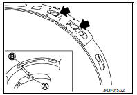
2. Pinch projection on the band with suitable pliers to tighten band.
3. Insert the tip of band into the lower part of pawl (marked with dotted circle) as shown in the figure.
For crimping type band • Secure the large and small ends of the boot with boot bands using the boot band crimping tool (A) (SST: KV40107300).
CAUTION:
• Never reuse boot band.
• Secure boot band so that dimension (A) meets the specification as shown in the figure.
A : 5.0 mm (0.197 in) or less.
8. Check that displacement does not occur when boot is rotated with the housing assembly fixed.
CAUTION:
• Reinstall them using boot bands when boot installation
positions become incorrect.
• Never reuse boot band.
9. Install dynamic damper, follow the procedure described below.
a. Install dynamic damper to the shaft of housing assembly.
• For installation position by shape, refer to the table below.
NOTE
:
Left side has 1 dynamic damper and 2 on the right side.
b. Install dynamic damper as shown in the figure and fix with band.
CAUTION:
Never reuse boot band.
Dynamic damper installation position: : FAX-60, "Drive Shaft".
• Left side
• Right side 10. Install dust shield to housing assembly.
CAUTION:
Never reuse dust shield.
11. Install circular clip to housing.
CAUTION:
Never reuse circular clip.
12. Install boot to the wheel side. Refer to FAX-54, "WHEEL SIDE : Disassembly and Assembly".
Inspection
INSPECTION AFTER REMOVAL
Check the following items, and replace the part if necessary.
• Move joint up/down, left/right, and in the axial directions. Check for motion that is not smooth and for significant looseness.
• Check boot for cracks, damage, and leakage of grease.
INSPECTION AFTER DISASSEMBLY
Check the following items, and replace the part if necessary.
Joint Sub-Assembly
Check the following:
• Joint sub-assembly for rough rotation and excessive axial looseness.
• The inside of the joint sub-assembly for entry of foreign material.
• Joint sub-assembly for compression scars, cracks, and fractures inside of joint sub-assembly.
Replace joint sub-assembly if there are any non-standard conditions of components.
Housing assembly
• Replace housing assembly if there is scratching or wear of housing roller
contact surface or spider roller
contact surface.
• Check shaft for runout, cracks, or other damage.
Dynamic Damper
Check damper for cracks or wear.
INSPECTION AFTER INSTALLATION
1. Check wheel sensor harness for proper connection. Refer to BRC-84, "FRONT WHEEL SENSOR : Exploded View" (Without ESP) or BRC-224, "FRONT WHEEL SENSOR : Exploded View" (With ESP).
2. Check the wheel alignment. Refer to FSU-7, "Inspection".
 Front drive shaft boot
Exploded View
LEFT SIDE
1. Circular clip
2. Dust shield
3. Housing assembly
4. Boot band
5. Boot
6. Damper band
7. Dynamic damper
8. Circular clip
9. Joint sub-assembly
: Wheel side ...
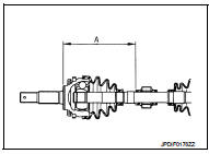
 Service data and specifications (SDS)
Wheel Bearing
Drive Shaft
M/T
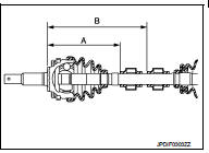
*: For measuring position, refer to FAX-54, "WHEEL SIDE : Disassembly and
Assembly" (Wheel side), FAX-
56, "TRANSAXLE SIDE : Disassembly and Asse ...
Other materials:
B257B, B257C ambient sensor
DTC Logic
DTC DETECTION LOGIC
NOTE:
• If DTC is displayed along with DTC U1000, first perform the trouble diagnosis
for DTC U1000. Refer to HAC-
141, "DTC Logic".
• If DTC is displayed along with DTC U1010, first perform the trouble diagnosis
for DTC U1010. HAC-142,
"DTC ...
USB/iPod charging ports
Type-A USB connection and charging port
There are dedicated USB/iPod charging ports conveniently located behind the center console for rear passengers. These ports are designed to charge compatible devices and mobile phones quickly while traveling in your N ...
Off position warning does not operate
Diagnosis Procedure
1.CHECK DTC WITH BCM AND COMBINATION METER
Check that DTC is not detected with BCM and combination meter.
Is the inspection result normal?
YES >> GO TO 2.
NO-1 >> Refer to BCS-67, "DTC Index". (BCM)
NO-2 >> Refer to MWI-36, "DTC Index&qu ...
