Nissan Juke Service and Repair Manual : P0840 transmission fluid pressure SEN/SW A
DTC Logic
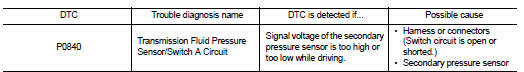
DTC DETECTION LOGIC
DTC CONFIRMATION PROCEDURE
NOTE
:
If ŌĆ£DTC CONFIRMATION PROCEDUREŌĆØ has been previously performed, always turn
ignition switch
OFF and wait at least 10 seconds before performing the next test.
After the repair, perform the following procedure to confirm the malfunction is eliminated.
1.CHECK DTC DETECTION
 With CONSULT-III
1. Turn ignition switch ON.
2. Select ŌĆ£DATA MONITORŌĆØ in ŌĆ£TRANSMISSIONŌĆØ.
3. Make sure that output voltage of line temperature sensor is within the range below.
ATF TEMP SEN : 1.0 ŌĆō 2.0 V If out of range, drive the vehicle to decrease the voltage (warm up the fluid) or stop engine to increase the voltage (cool down the fluid)
4. Start engine and wait for at least 5 consecutive seconds.
 With GST
Follow the procedure ŌĆ£With CONSULT-IIIŌĆØ.
Is ŌĆ£P0840ŌĆØ detected? YES >> Go to TM-230, "Diagnosis Procedure".
NO >> Check intermittent incident. Refer to GI-42, "Intermittent Incident".
Diagnosis Procedure
1.CHECK INPUT SIGNAL
1. Start engine.
2. Check voltage between TCM connector terminal and ground.
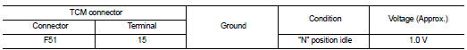
Is the inspection result normal? YES >> GO TO 6.
NO >> GO TO 2.
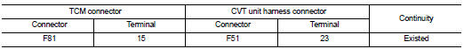
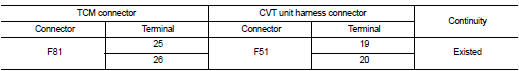
2.CHECK HARNESS BETWEEN TCM AND SECONDARY PRESSURE SENSOR
1. Turn ignition switch OFF.
2. Disconnect TCM connector and CVT unit harness connector.
3. Check continuity between TCM connector terminal and CVT unit harness connector terminal.
4. If OK, check harness for short to ground and short to power.
5. Reinstall any part removed.
Is the inspection result normal? YES >> GO TO 3.
NO >> Repair or replace damaged parts.
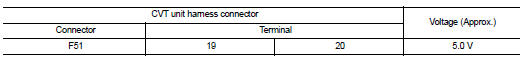
3.CHECK SENSOR POWER AND SENSOR GROUND
1. Connect TCM connector.
2. Turn ignition switch ON.
3. Check voltage between CVT unit harness connector terminals.
4. Reinstall any part removed.
Is the inspection result normal? YES >> GO TO 5.
NO >> GO TO 4.
4. CHECK HARNESS BETWEEN TCM AND CVT UNIT HARNESS CONNECTOR (SENSOR POWER AND SENSOR GROUND)
1. Turn ignition switch OFF.
2. Disconnect TCM connector.
3. Check continuity between TCM connector terminals and CVT unit harness connector terminals.
4. If OK, check harness for short to ground and short to power.
5. Reinstall any part removed.
Is the inspection result normal? YES >> GO TO 5.
NO >> Repair or replace damaged parts.
5. CHECK THE TCM SHORT
Replace same type TCM, perform self-diagnosis check. Erase self-diagnostic results and then start engine perform self-diagnosis check. Refer to TM-230, "DTC Logic".
Is ŌĆ£P0840ŌĆØ detected again? YES >> Replace the transaxle assembly. Refer to TM-301, "Removal and Installation".
NO >> Replace the TCM. Refer to TM-280, "Removal and Installation".
6.CHECK TCM
Check TCM input/output signals. Refer to TM-164, "Reference Value".
Is the inspection result normal? YES >> Check intermittent incident. Refer to GI-42, "Intermittent Incident".
NO >> Replace the TCM. Refer to TM-280, "Removal and Installation".
 P0826 up and down shift SW
DTC Logic
DTC DETECTION LOGIC
DTC CONFIRMATION PROCEDURE
CAUTION:
Always drive vehicle at a safe speed.
NOTE:
If ŌĆ£DTC CONFIRMATION PROCEDUREŌĆØ has been previously conducted, always turn
i ...
 P0841 transmission fluid pressure SEN/SW A
Description
Using the engine load (throttle position), the primary pulley revolution
speed, and the secondary pulley revolution
speed as input signal, TCM changes the operating pressure of the pri ...
Other materials:
Service data and specifications (SDS)
General Specifications
Steering Wheel Axial End Play and Play
Steering Wheel Turning Force
Steering Angle
Steering Column Operating Range
*: For measuring position, refer to ST-11, "Inspection".
Rack Stroke
Socket Swing Force
*: For measuring position, refer to ST-21, ...
Air cleaner and air duct
Exploded View
1. Turbocharger air inlet pipe
2. Clamp
3. Air duct (suction)
4. Air mass flow sensor
5. O-ring
6. Air duct (inlet)
7. Grommet
8. Air cleaner case
9. Air cleaner filter
10. Cover
11. Holder
A. : To turbocharger
: Vehicle front
: N┬Ęm (kg-m, in-lb)
: Always repla ...
Fog light switch (if so equipped)
To turn the fog lights on, turn the headlight switch to the
position, then turn the switch to the
position. To turn them off, turn the
switch to the OFF position.
The headlights must be on for the fog lights to operate.
When the headlight switch is in the AUTO position, turning the fog lig ...
