Nissan Juke Service and Repair Manual : Harness layout
LHD
LHD : How To Read Harness Layout
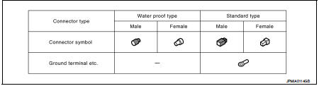
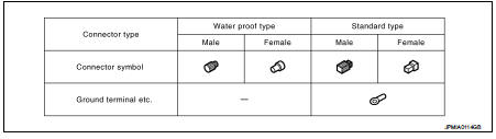
CONNECTOR SYMBOL
Main symbols of connector (in Harness Layout) are indicated in the below.
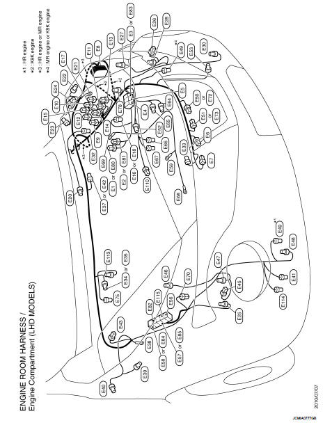
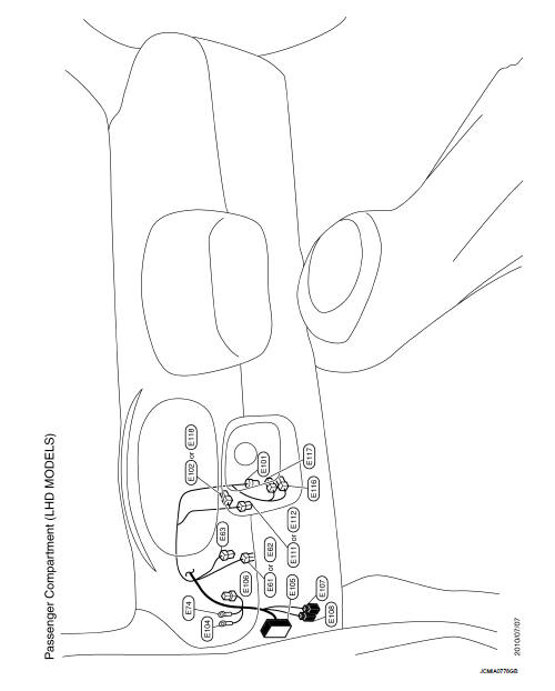
LHD : Engine Room Harness
ENGINE COMPARTMENT
PASSENGER COMPARTMENT
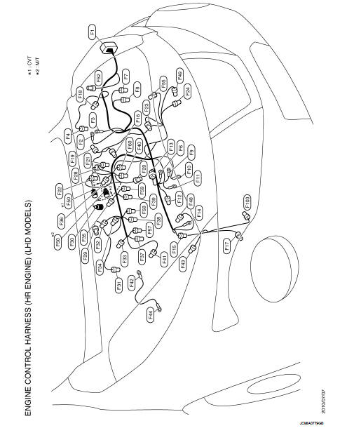
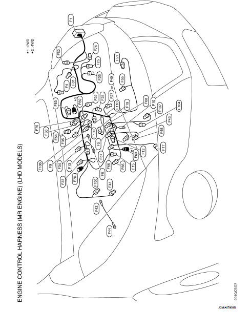
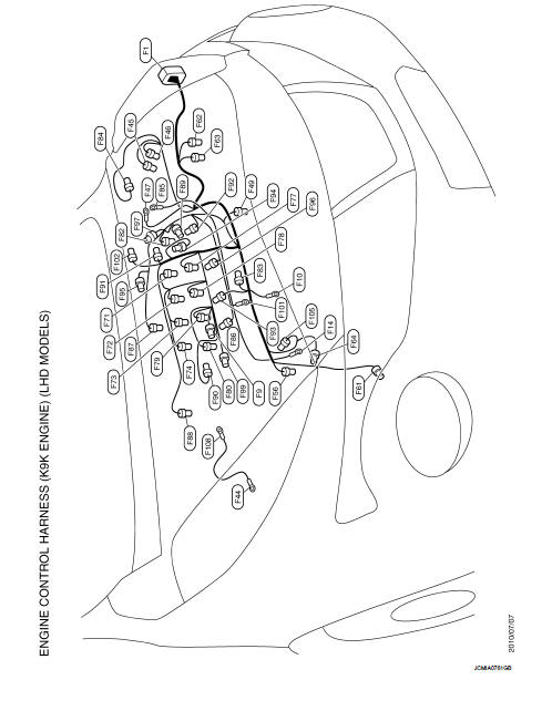
LHD : Engine Control Harness
HR ENGINE
MR ENGINE
K9K ENGINE
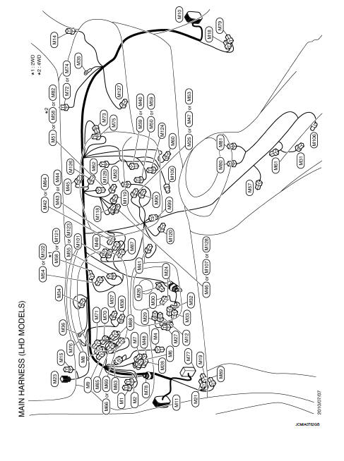
LHD : Main Harness
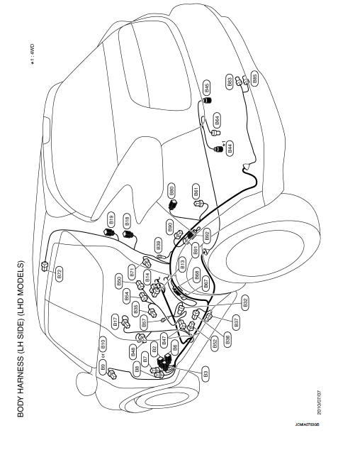
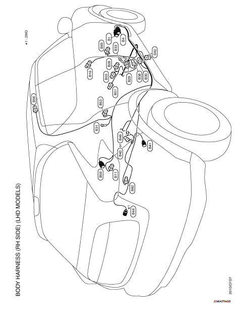
LHD : Body Harness
LH SIDE
RH SIDE
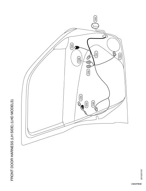
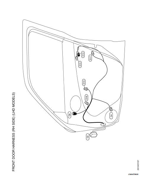
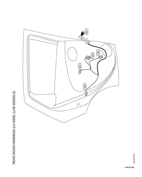
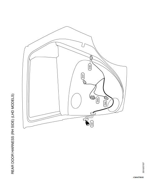
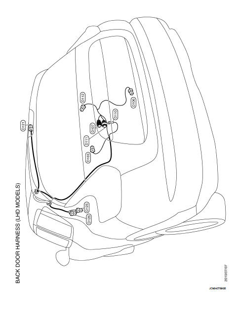
LHD : Door Harness
FRONT DOOR HARNESS (LH SIDE)
FRONT DOOR HARNESS (RH SIDE)
REAR DOOR HARNESS (LH SIDE)
REAR DOOR HARNESS (RH SIDE)
BACK DOOR HARNESS
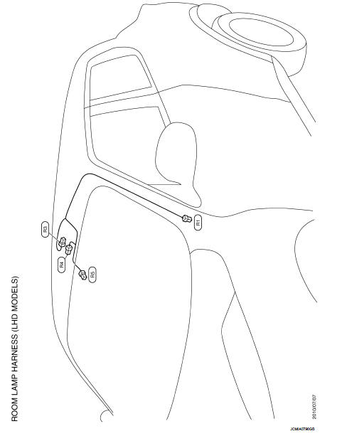
LHD : Room Lamp Harness
RHD
RHD : How To Read Harness Layout
CONNECTOR SYMBOL
Main symbols of connector (in Harness Layout) are indicated in the below.
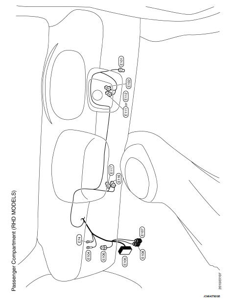
RHD : Engine Room Harness
ENGINE COMPARTMENT
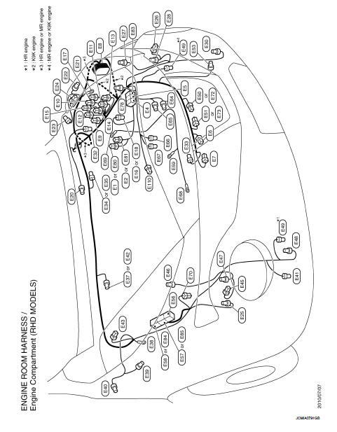
PASSENGER COMPARTMENT
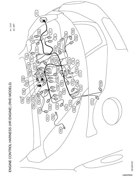
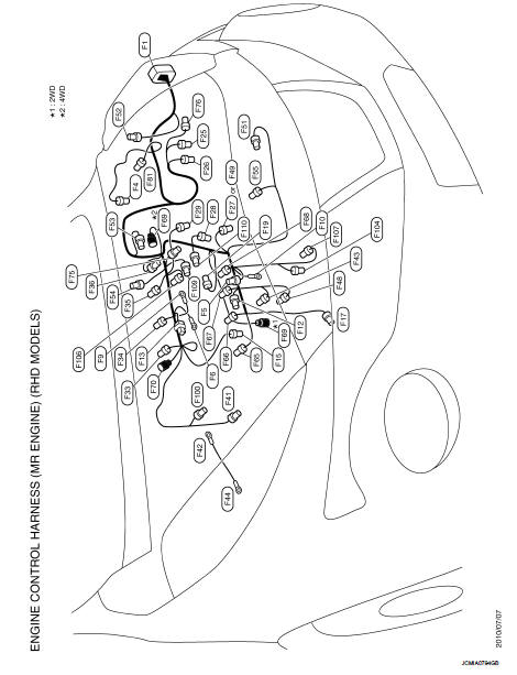
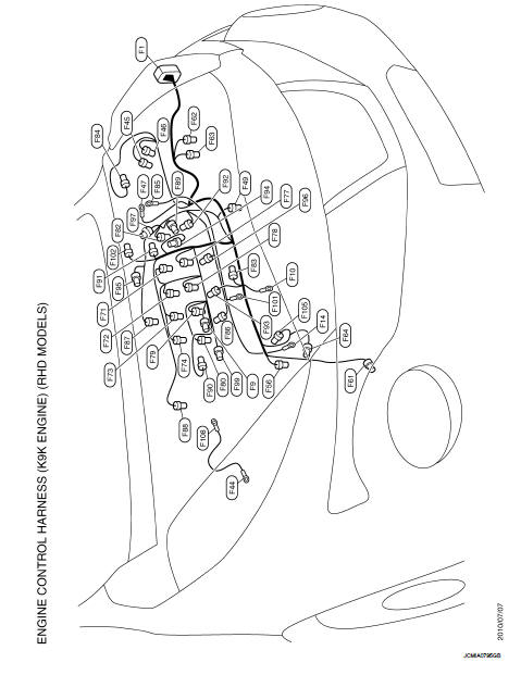
RHD : Engine Control Harness
HR ENGINE
MR ENGINE
K9K ENGINE
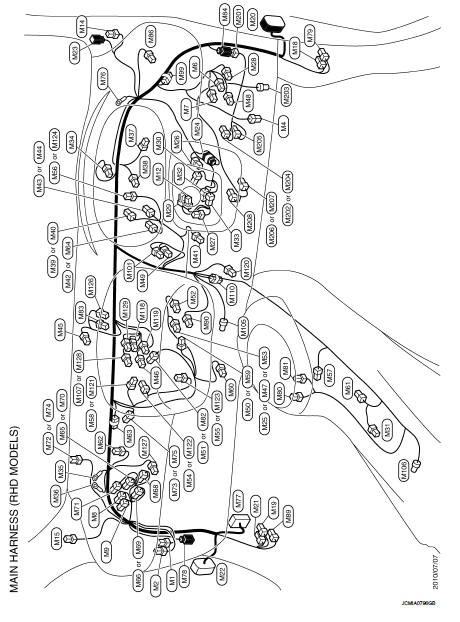
RHD : Main Harness
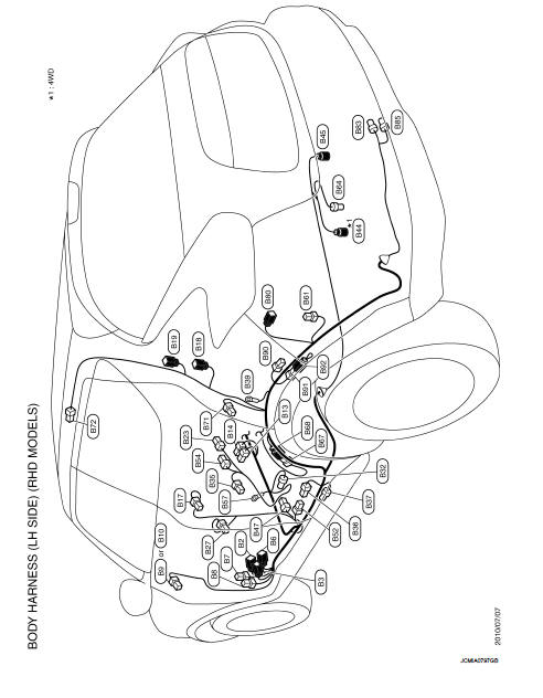
RHD : Body Harness
LH SIDE
RH SIDE

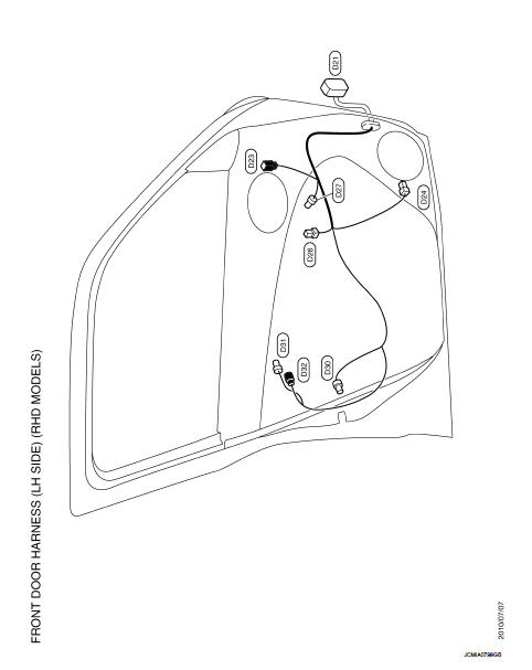
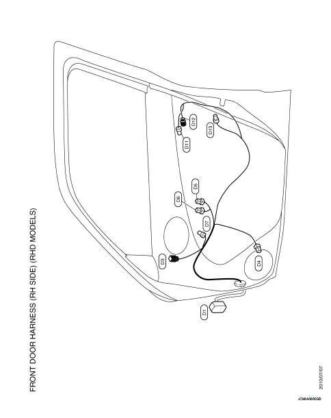
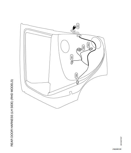
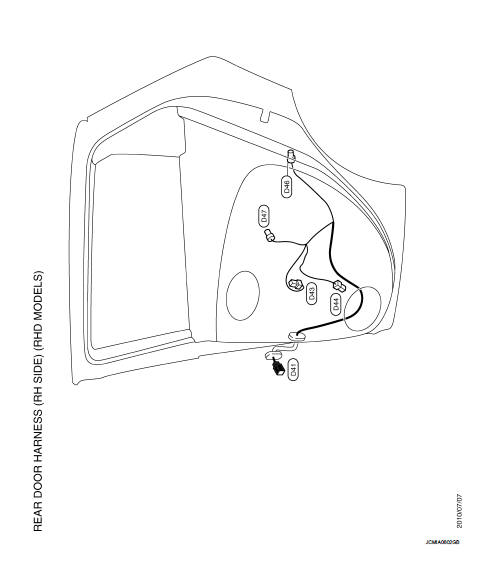
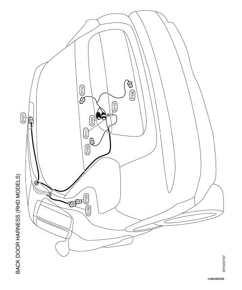
RHD : Door Harness
FRONT DOOR HARNESS (LH SIDE)
FRONT DOOR HARNESS (RH SIDE)
REAR DOOR HARNESS (LH SIDE)
REAR DOOR HARNESS (RH SIDE)
BACK DOOR HARNESS
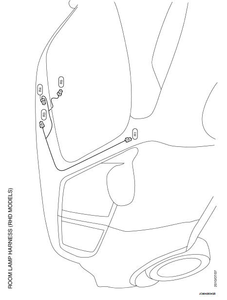
RHD : Room Lamp Harness
 IPDM E/R (intelligent power distribution module engine
room)
IPDM E/R (intelligent power distribution module engine
room)
Fuse, Connector and Terminal Arrangement
...
 Connector information
How to Read Connector Type
1 : Connector model
2 : Cavity
3 : Male (M) and female (F) terminals
4 : Connector color
5 : Special type
B Body Harness
D Door Harness
...
Other materials:
Unbalance steering wheel turning force and return between
right and left
Description
Unbalance steering wheel turning force and return between right and left.
Diagnosis Procedure
1.CHECK THE ILLUMINATION OF THE EPS WARNING LAMP
Check the EPS warning lamp while engine is running.
Does the EPS warning lamp turn OFF?
YES >> GO TO 2.
NO >> Refer to STC ...
Fuel-filler cap
To remove the fuel-filler cap:
1. Turn the fuel-filler cap counterclockwise 1 to remove.
2. Put the fuel-filler cap on the cap holder A while refueling.
To install the fuel-filler cap:
1. Insert the fuel-filler cap straight into the fuelfiller tube.
2. Turn the fuel-filler cap clockwise 2 unt ...
C1109 power and ground system
DTC Logic
DTC DETECTION LOGIC
DTC CONFIRMATION PROCEDURE
1.PRECONDITIONING
If ŌĆ£DTC CONFIRMATION PROCEDUREŌĆØ has been previously conducted, always turn
ignition switch OFF and
wait at least 10 seconds before conducting the next test.
>> GO TO 2.
2.CHECK DTC DETECTION
With CON ...
