
Nissan Juke Service and Repair Manual : Connector information
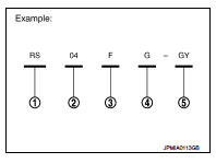
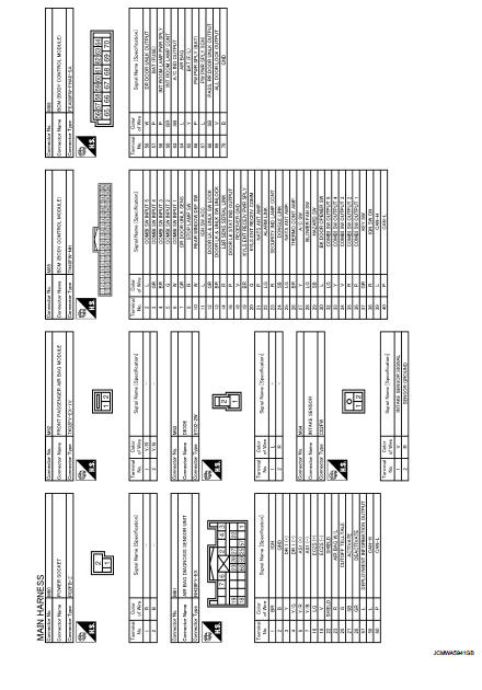
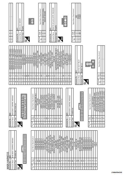
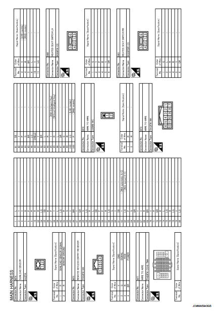
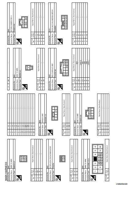
How to Read Connector Type
1 : Connector model
2 : Cavity
3 : Male (M) and female (F) terminals
4 : Connector color
5 : Special type
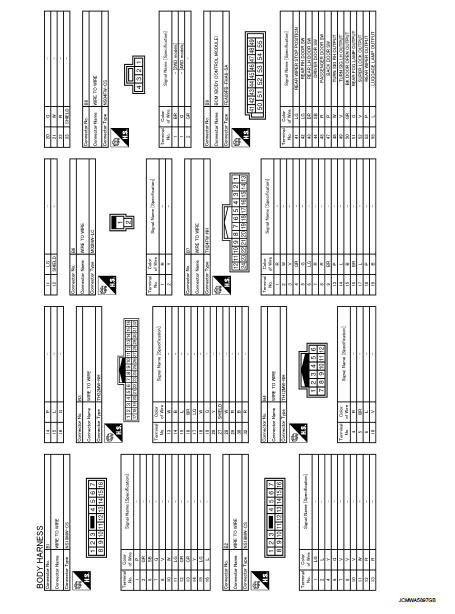
B Body Harness
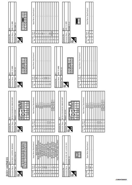
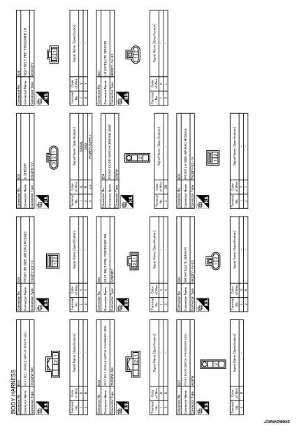
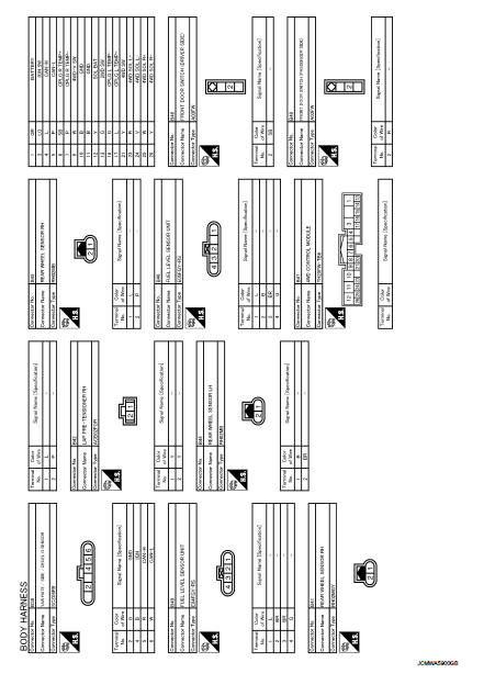
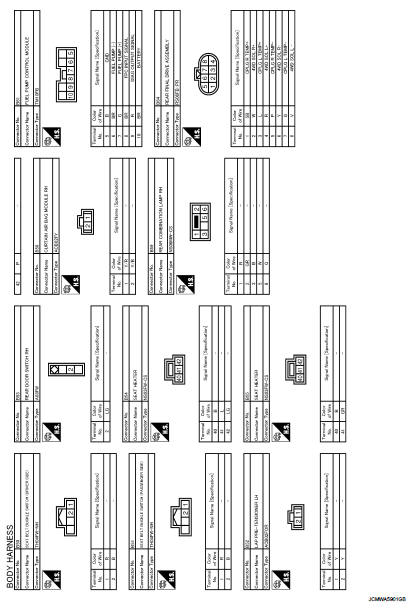
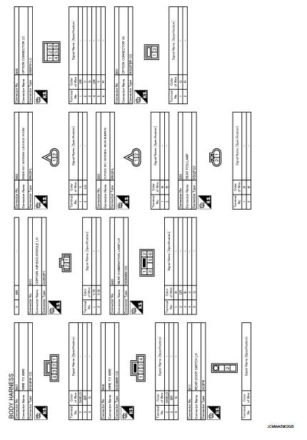
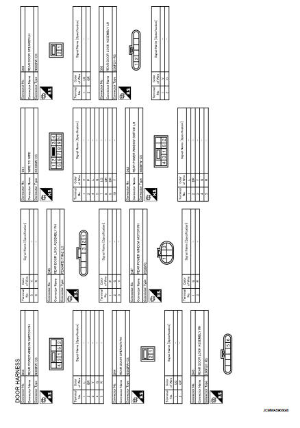
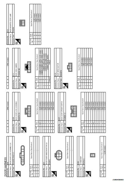
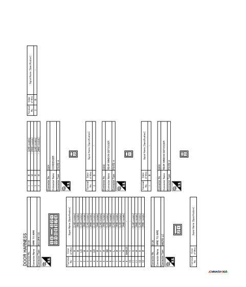
D Door Harness
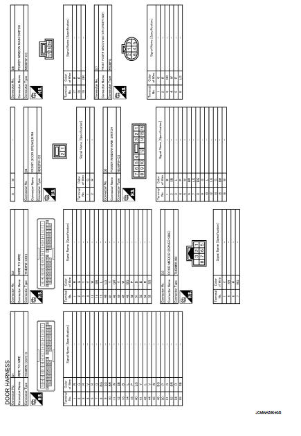
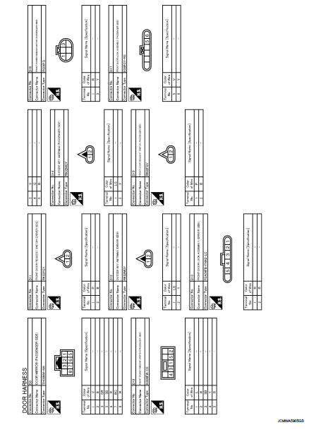
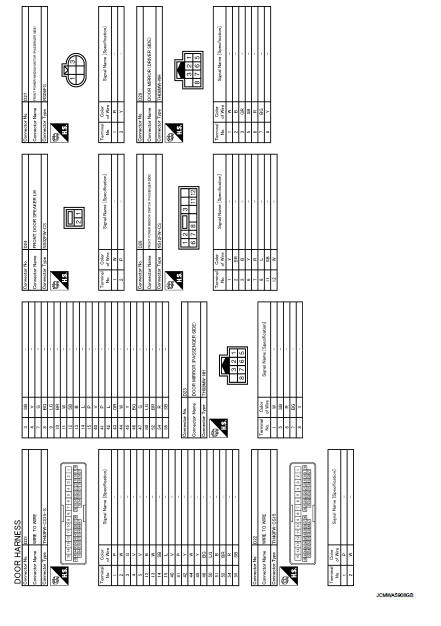
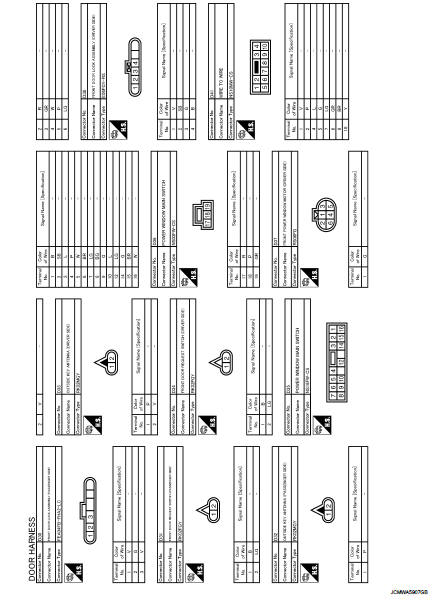
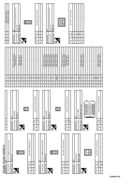
E Engine Room Harness
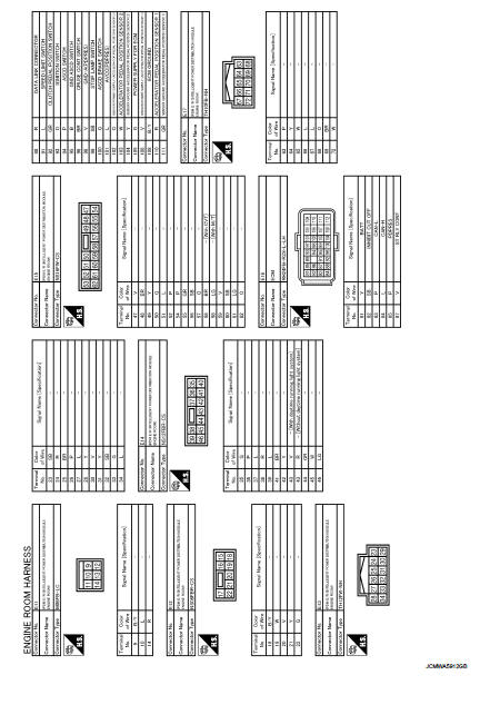
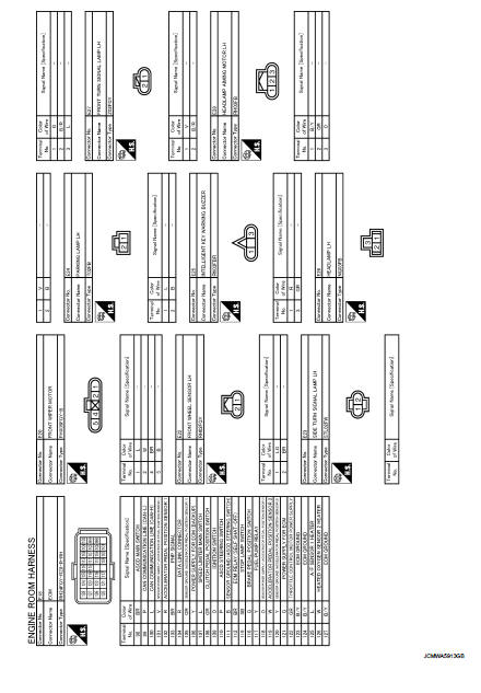

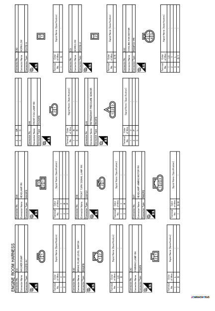
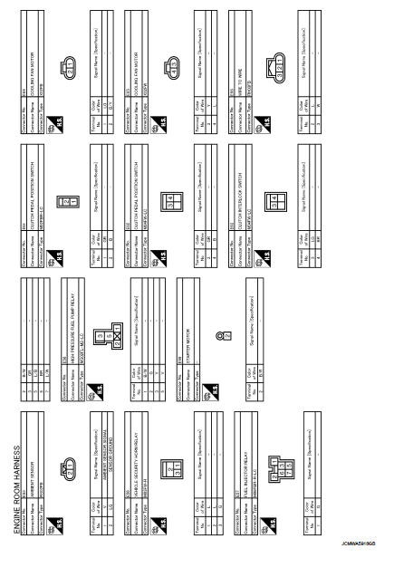
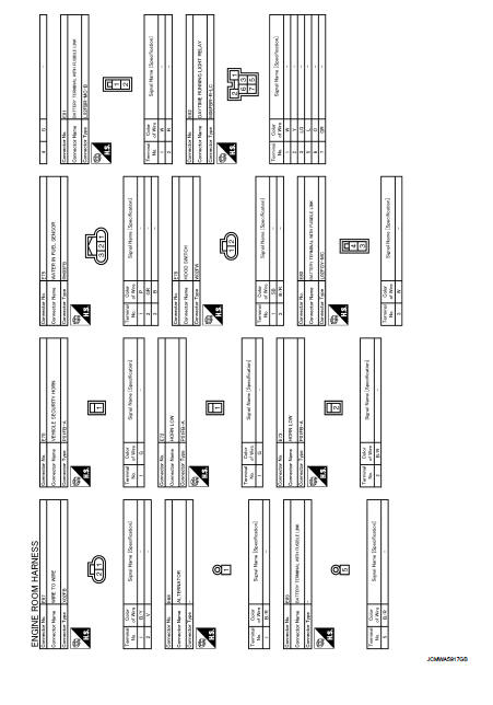
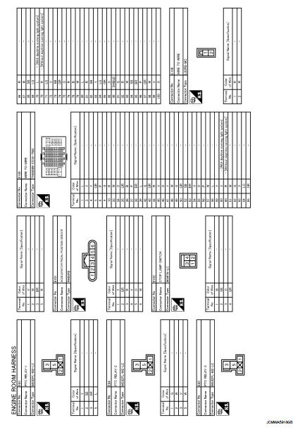
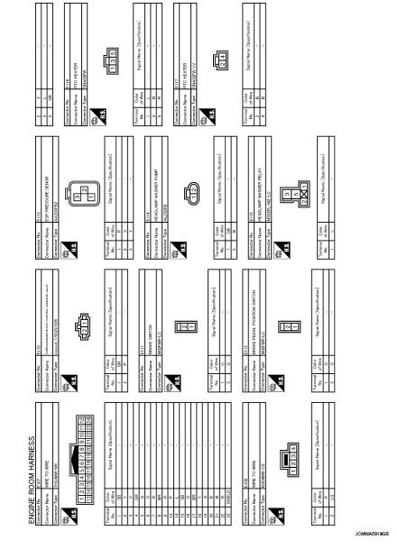
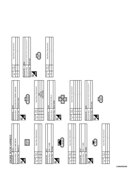
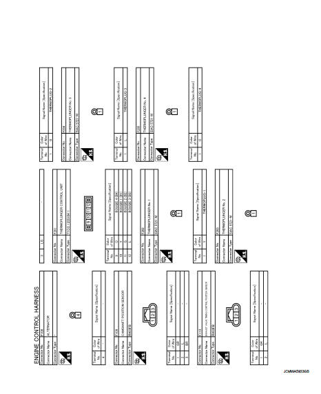
F Engine Control Harness
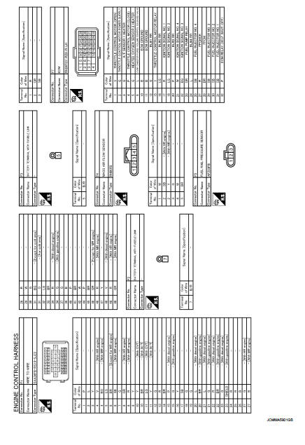
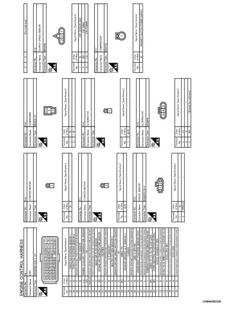
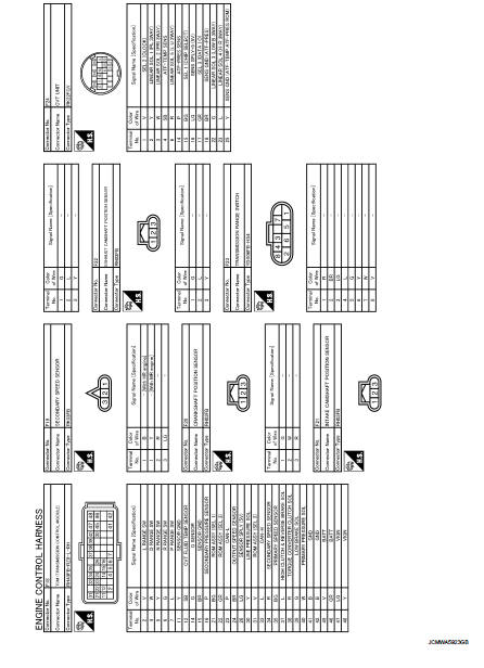
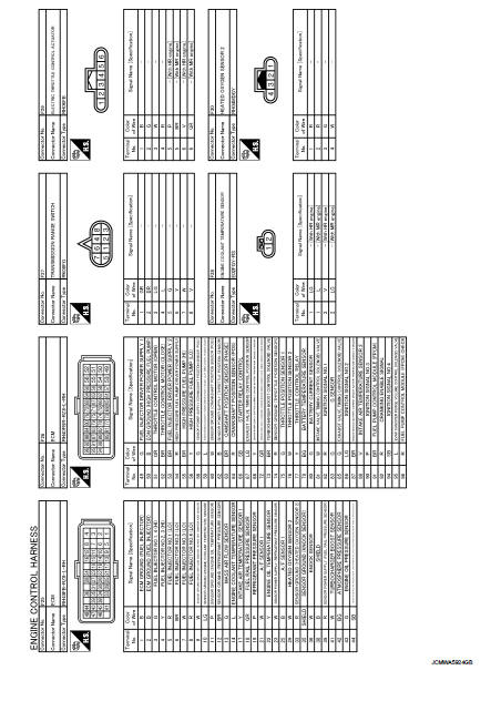
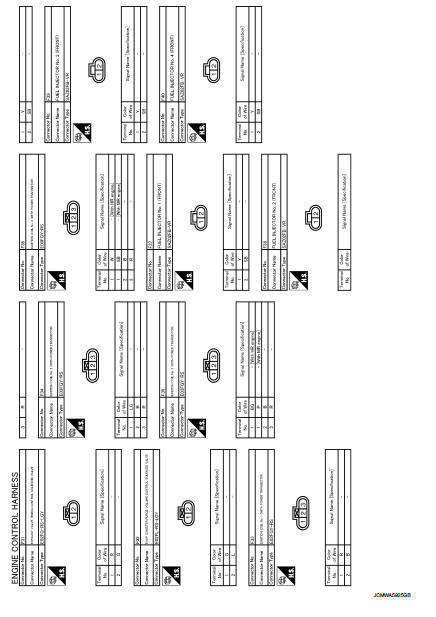
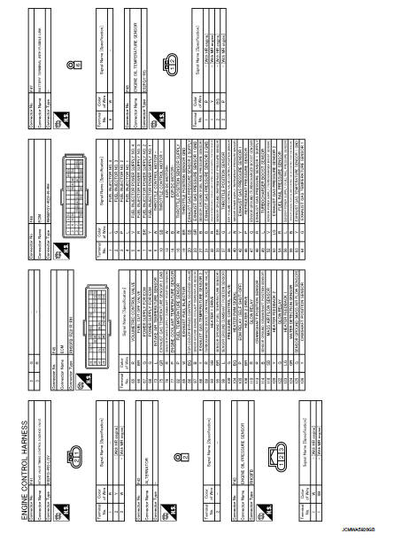
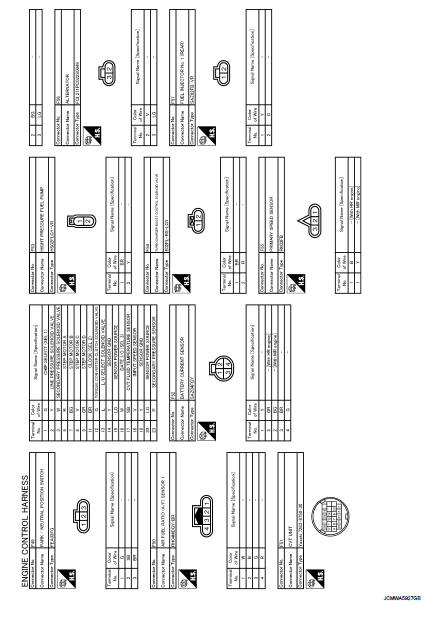
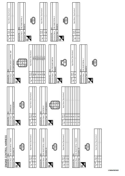
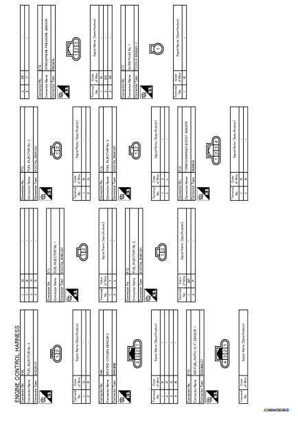
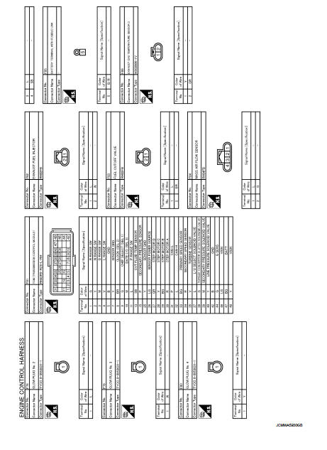
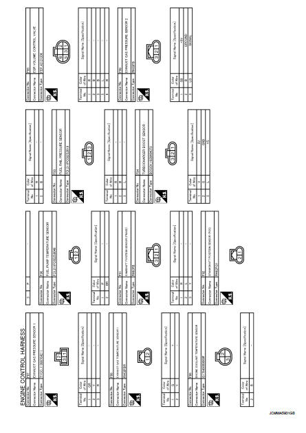
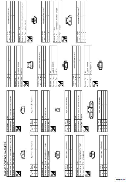
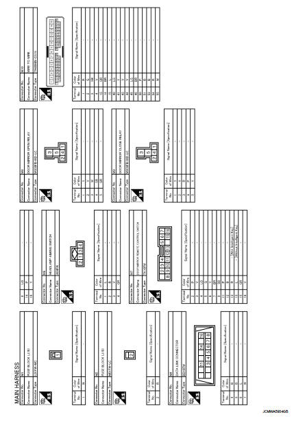
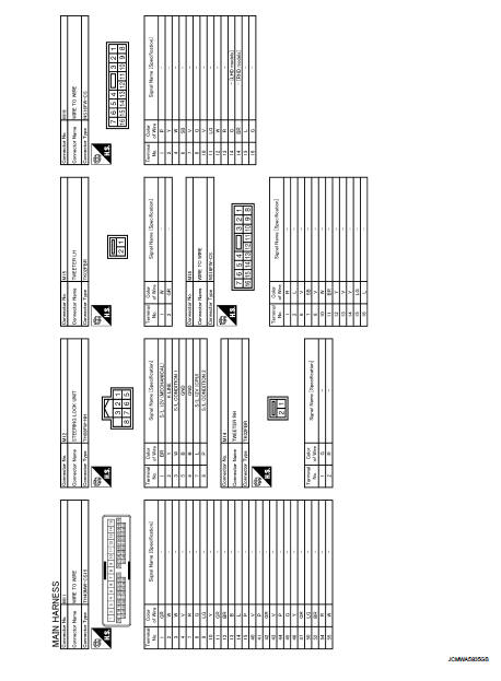
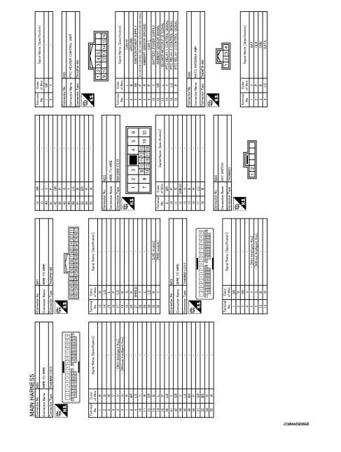
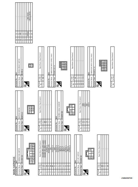
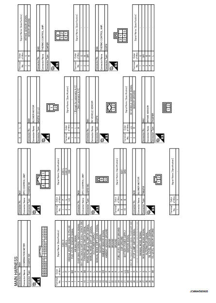
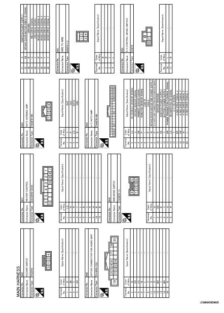
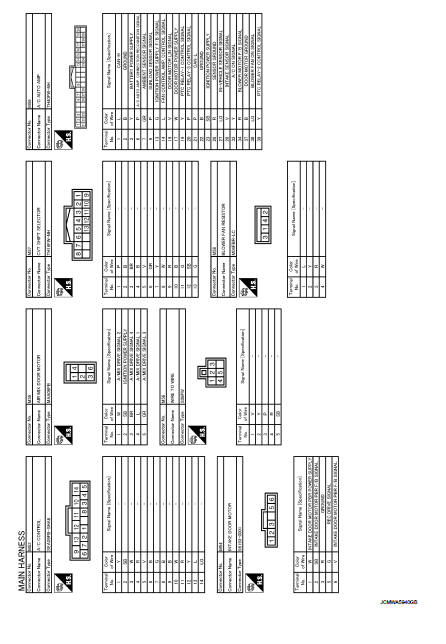
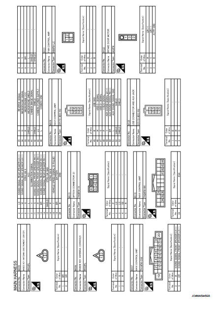
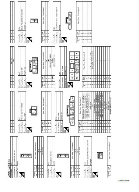
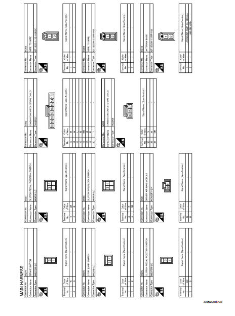
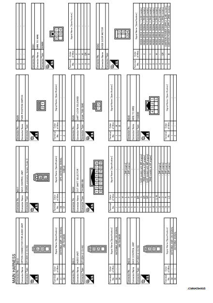
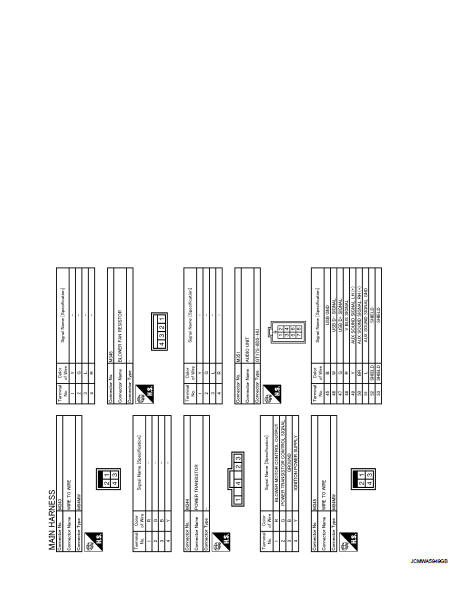
M Main Harness
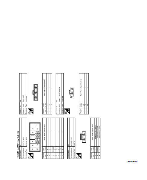
R Room Lamp Harness
 Harness layout
LHD
LHD : How To Read Harness Layout
CONNECTOR SYMBOL
Main symbols of connector (in Harness Layout) are indicated in the below.
LHD : Engine Room Harness
ENGINE COMPARTMENT
PASSENGER COMPART ...
 Basic inspection
...
Other materials:
RCTA system operation
Side Indicator Light
The RCTA system acts as an extra set of eyes, helping to alert the driver to approaching traffic while reversing out of a parking stall or driveway.
The system becomes active when the shift position is set to R (Reverse) ...
Wiring diagram
POWER DISTRIBUTION SYSTEM
LHD
LHD : Wiring Diagram
For connector terminal arrangements, harness layouts, and alphabets in a
(option abbreviation; if not
described in wiring diagram), refer to GI-12, "Connector Information/Explanation
of Option Abbreviation".
RHD
RHD : Wiring D ...
Fuel filler lid opener
Exploded View
1. Fuel filler lid opener cable
2. Cable protector
3. Fuel filler lid lock assembly
4. Fuel filler lid assembly
5. Spring
6. Bumper rubber
: Clip
: Do not reuse
Fuel filler lid
FUEL FILLER LID : Removal and Installation
REMOVAL
1. Fully open fuel filler lid.
2. Remov ...
