Nissan Juke Service and Repair Manual : P062B ECM
Description
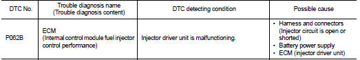
This DTC is detected when the ECM-integrated injector driver unit has a malfunction. For injector driver unit, refer to EC-31, "ECM".
DTC Logic
DTC DETECTION LOGIC
DTC CONFIRMATION PROCEDURE
1.PRECONDITIONING
1. Turn ignition switch OFF and wait at least 10 seconds.
2. Turn ignition switch ON.
3. Turn ignition switch OFF and wait at least 10 seconds.
TESTING CONDITION:
Before performing the following procedure, confirm that battery voltage is 11 V
or more at idle
.
>> GO TO 2.
2.PERFORM DTC CONFIRMATION PROCEDURE
1. Start the engine and keep the engine speed at idle for 30 seconds.
2. Check 1st trip DTC.
Is 1st trip DTC detected? YES >> Proceed to EC-306, "Diagnosis Procedure".
NO >> INSPECTION END
Diagnosis Procedure
1.CHECK FUEL INJECTOR
Check fuel injector. Refer toEC-400, "Component Function Check".
Is inspection result normal? YES >> GO TO 2.
NO >> Repair or replace error-detected parts.
2.PERFORM DTC CONFIRMATION PROCEDURE
1. Turn ignition switch ON.
2. Erase DTC.
3. Perform DTC confirmation procedure again. Refer to EC-306, "DTC Logic".
4. Check 1st trip DTC.
Is the DTC P062B displayed again? YES >> Replace ECM. Refer to EC-447, "Removal and Installation".
NO >> INSPECTION END
 P0611 ECM protection
Description
This DTC is detected when the ECM protective function is activated due to an
extreme temperature increase
in ECM, resulting from severe conditions such as heavy load driving.
DTC Logi ...
 P0643 sensor power supply
DTC Logic
DTC DETECTION LOGIC
DTC CONFIRMATION PROCEDURE
1.PRECONDITIONING
If DTC Confirmation Procedure has been previously conducted, always perform
the following procedure
before conductin ...
Other materials:
Precaution for Supplemental Restraint System (SRS) "AIR BAG" and "SEAT BELT
PRE-TENSIONER"
The Supplemental Restraint System such as “AIR BAG” and “SEAT BELT PRE-TENSIONER”,
used along
with a front seat belt, helps to reduce the risk or severity of injury to the
driver and front passenger for certain
types of collision. Information necessary to service the system safely is
...
Intelligent Lane Intervention (I-LI)
WARNING
Failure to strictly follow the safety warnings and operational instructions for the proper use of the I-LI system could result in an unintended vehicle path, loss of control, and subsequent serious injury or death.
The I-LI system is a driver-assist ...
Connector Symbols
Most of connector symbols in wiring diagrams are shown from the terminal
side.
• Connector symbols shown from the terminal side are enclosed by
a single line and followed by the direction mark.
• Connector symbols shown from the harness side are enclosed by
a double line and followed by ...
