Nissan Juke Service and Repair Manual : P0643 sensor power supply
DTC Logic
DTC DETECTION LOGIC

DTC CONFIRMATION PROCEDURE
1.PRECONDITIONING
If DTC Confirmation Procedure has been previously conducted, always perform the following procedure before conducting the next test.
1. Turn ignition switch OFF and wait at least 10 seconds.
2. Turn ignition switch ON.
3. Turn ignition switch OFF and wait at least 10 seconds.
TESTING CONDITION:
Before performing the following procedure, confirm that battery voltage is more
than 8 V at idle.
>> GO TO 2.
2.PERFORM DTC CONFIRMATION PROCEDURE
1. Start engine and let it idle for 1 second.
2. Check DTC.
Is DTC detected? YES >> Proceed to EC-307, "Diagnosis Procedure".
NO >> INSPECTION END
Diagnosis Procedure
1.CHECK SENSOR POWER SUPPLY
1. Turn ignition switch ON.
2. Check the voltage between ECM harness connector and ground.

Is the inspection result normal?
YES >> Check intermittent incident. Refer to GI-42, "Intermittent Incident".
NO >> GO TO 2.
2.CHECK SENSOR POWER SUPPLY ROUTING CIRCUIT FOR SHORT
1. Turn ignition switch OFF.
2. Check harness for short to power and to ground, between the following terminals.
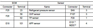
*1: LHD models or RHD with CVT models *2: RHD with M/T models
Is the inspection result normal? YES >> GO TO 3.
NO >> Repair or replace error-detected parts.
3.CHECK COMPONENT
S
Check the following.
• Refrigerant pressure sensor Refer to EC-423, "Diagnosis Procedure".
• Crankshaft position sensor Refer to EC-273, "Component Inspection".
• Throttle position sensor Refer to EC-203, "Component Inspection".
• Accelerator pedal position sensor Refer to EC-387, "Component Inspection".
Is the inspection result normal? YES >> Check intermittent incident. Refer to GI-42, "Intermittent Incident".
NO >> Replace malfunctioning component.
 P062B ECM
Description
This DTC is detected when the ECM-integrated injector driver unit has a
malfunction. For injector driver unit,
refer to EC-31, "ECM".
DTC Logic
DTC DETECTION LOGIC
DTC C ...
 P0850 PNP switch
Description
For CVT models, transmission range switch is turn ON when the selector lever
is P or N.
For M/T models, park/neutral position (PNP) range switch is ON when the selector
lever is Ne ...
Other materials:
U0122 Vehicle dynamics control
module
Description
CAN (Controller Area Network) is a serial communication line for real time
application. It is an on-vehicle multiplex
communication line with high data communication speed and excellent error
detection ability. Many electronic
control units are equipped onto a vehicle, and each c ...
Thermostat
Exploded View
1. Thermostat housing
2. Gasket
3. Rubber ring
4. Thermostat
5. Water inlet
6. Clamp
7. Radiator hose (upper)
A. To radiator
Engine front
: N·m (kg-m, ft-lb)
: Always replace after every
disassembly.
Removal and Installation
REMOVAL
1. Drain engine coolant from ...
Charge connector lock system
To provide enhanced security and peace of mind during public charging sessions, the Nissan Leaf is equipped with an integrated charge connector lock system. This feature allows you to securely lock your normal or trickle charge connector to the vehicle's charge port, preventing ...
