Nissan Juke Service and Repair Manual : Outside mirror
Exploded View
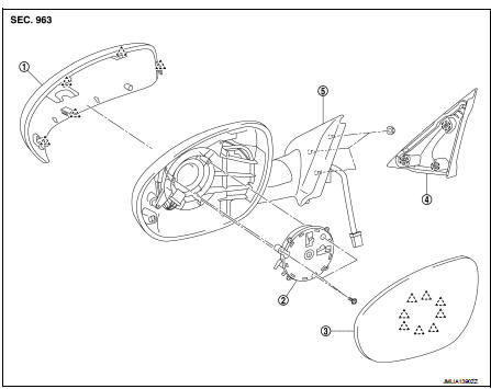
1. Door mirror cover
2. Actuator
3. Glass mirror
4. Door mirror corner cover
5. Door mirror assembly
 : Clip
 : Pawl
Door mirror assembly
DOOR MIRROR ASSEMBLY : Removal and Installation
CAUTION:
When removing, always use a remover tool that is made of plastic.
REMOVAL
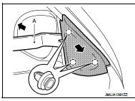
1. Disengage door mirror corner cover fixing clips with a remover tool (A) and then remove door mirror corner cover.
 : Clip
2. Remove front door finisher. Refer to INT-13, "Removal and Installation".
3. Disconnect door mirror harness connector.
4. Remove door mirror mounting nuts, and then remove door mirror assembly.
INSTALLATION
Install in the reverse order of removal.
Glass mirror
GLASS MIRROR : Removal and Installation
REMOVAL
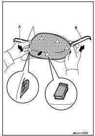
1. Place the glass mirror upward.
2. Put a strip of protective tape (B) on mirror body (1).
3. Insert a small flat-bladed screwdriver (A) into the recess at lower side between glass mirror (2) and actuator, and push up pawls to remove glass mirror lower side.
NOTE
:
Insert a small flat-bladed screwdriver into recesses, and push up
while rotating (twisting) to make work easier.
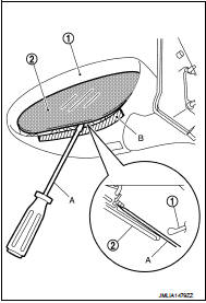
4. Remove glass mirror from mirror body.
INSTALLATION
Note the following item, and then install in the reverse order of removal.
CAUTION:
After installation, visually check that pawls are securely engaged.
Door mirror cover
DOOR MIRROR COVER : Removal and Installation
REMOVAL
1. Remove door mirror assembly from the door panel. Refer to MIR-43, "DOOR MIRROR ASSEMBLY : Removal and Installation".
2. Remove the glass mirror. Refer to MIR-44, "GLASS MIRROR : Removal and Installation".
3. Disengage door mirror cover fixing pawls while pressing the pawls toward the direction of the arrows.
 : Pawl
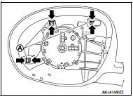
4. Insert two remover tools (A) and (B) between door mirror cover and mirror body to disengage the pawls, and then remove door mirror cover.
 : Pawl
5. Remove actuator fixing screws (A).
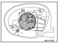
6. Disconnect actuator harness connector and then remove actuator from door mirror.
INSTALLATION
Note the following item and then install in the reverse order of removal.
CAUTION:
After installation, visually check that pawls are securely engaged.
 Inside mirror
Exploded View
Manual anti-dazzling type
1. Windshield glass
2. Mirror base
3. Inside mirror assembly
: Do not reuse
Auto anti-dazzling type
1. Rain sensor bracket
2. Mirror base
3. Ra ...
 Door mirror remote control switch
Exploded View
1. Instrument lower panel
2. Switch bracket
3. Door mirror remote control switch
Removal and Installation
REMOVAL
1. Remove the instrument lower panel. Refer to IP-13, "Re ...
Other materials:
Driver air bag module
Exploded View
1. Steering column upper cover
2. Steering column assembly
3. Steering column lower cover
4. Side lid LH
5. TORX bolt
6. Driver air bag module
7. TORX bolt
8. Side lid RH
9. Steering wheel
10. Spiral cable
11. Steering angle sensor
12. Combination switch
13. Stee ...
Headlamp washer pump
Exploded View
1. Front washer nozzle LH
2. Front washer nozzle RH
3. Front washer tube LH
4. Front washer tube RH
5. Check valve
6. Front washer tube
7. Joint
8. Washer tank inlet cap
9. Washer tank inlet
10. Washer tank
11. Headlamp washer pump
12. Washer pump
13. Packing
1 ...
P0717 input speed sensor A
DTC Logic
DTC DETECTION LOGIC
DTC CONFIRMATION PROCEDURE
CAUTION:
Always drive vehicle at a safe speed.
NOTE:
If ŌĆ£DTC CONFIRMATION PROCEDUREŌĆØ has been previously performed, always turn
ignition switch
OFF and wait at least 10 seconds before performing the next test.
After the repai ...
