Nissan Juke Service and Repair Manual : Liquid Gasket
REMOVAL OF LIQUID GASKET SEALING
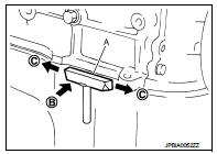
• After removing mounting nuts and bolts, separate the mating surface using the seal cutter [SST: KV10111100 (J-37228)] (A) and remove old liquid gasket sealing.
CAUTION
:
Be careful not to damage the mating surfaces.
• Tap the seal cutter [SST: KV10111100 (J-37228)] to insert it (B), and then slide it (C) by tapping on the side as shown in the figure.
• In areas where the seal cutter [SST: KV10111100 (J-37228)] is difficult to use, lightly tap the parts using a plastic hammer to remove it.
CAUTION:
If for some unavoidable reason tool such as a screwdriver is
used, be careful not to damage the mating surfaces.
LIQUID GASKET APPLICATION PROCEDURE
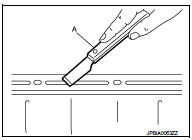
1. Using a scraper (A), remove old liquid gasket adhering to the liquid gasket application surface and the mating surface.
• Remove liquid gasket completely from the groove of the liquid gasket application surface, mounting bolts, and bolt holes.
2. Wipe the liquid gasket application surface and the mating surface with white gasoline (lighting and heating use) to remove adhering moisture, grease and foreign materials.
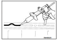
3. Attach liquid gasket tube to the tube presser (commercial service tool). Use Genuine Liquid Gasket or equivalent.
4. Apply liquid gasket without gaps to the specified location according to the specified dimensions.
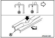
• If there is a groove for liquid gasket application, apply liquid gasket to the groove.
• As for bolt holes (B), normally apply liquid gasket inside the holes. Occasionally, it should be applied outside the holes.
Check to read the text of this manual.
A : Groove
: Inside
• Within five minutes of liquid gasket application, install the mating component.
• If liquid gasket protrudes, wipe it off immediately.
• Do not retighten mounting bolts or nuts after the installation.
• After 30 minutes or more have passed from the installation, fill engine oil and engine coolant.
CAUTION:
If there are specific instructions in this manual, observe them.
 Parts Requiring Angle Tightening
• Use the angle wrench [SST: KV10112100 (BT8653-A)] for the final tightening
of the following engine parts:
- Camshaft sprocket (INT) bolt
- Cylinder head bolts
- Main bearing cap bolts
- Conn ...
 Preparation
...
Other materials:
Refrigeration system symptoms
Trouble Diagnosis For Unusual Pressure
Diagnose using a manifold gauge whenever system’s high and/or low side
pressure(s) is/are unusual. The
marker above the gauge scale in the following tables indicates the standard
(usual) pressure range. Refer to
above table (Ambient air temperature-to- ...
Steering switch signal A circuit
Description
Transmits the steering switch signal to NAVI control unit.
Diagnosis Procedure
1.CHECK STEERING SWITCH SIGNAL A CIRCUIT
1. Disconnect NAVI control unit connector and spiral cable connector.
2. Check continuity between NAVI control unit harness connector and spiral cable
harness co ...
P1813 4WD mode switch
DTC Logic
DTC DETECTION LOGIC
DTC CONFIRMATION PROCEDURE
1.PRECONDITIONING
If “DTC CONFIRMATION PROCEDURE” has been previously conducted, always turn
ignition switch OFF and
wait at least 10 seconds before conducting the next test.
>> GO TO 2.
2.DTC REPRODUCTION PROCEDURE
W ...
