Nissan Juke Service and Repair Manual : Line pressure test
Inspection and Judgment
INSPECTION
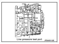
Line Pressure Test Port
Line Pressure Test Procedure 1. Inspect the amount of engine oil and replenish if necessary.
2. Drive the car for about 10 minutes to warm it up so that the CVT fluid reaches in the range of 50 to 80°C (122 to 176°F), then inspect the amount of CVT fluid and replenish if necessary.
NOTE
:
The CVT fluid temperature rises in the range of 50 to 80°C (122 to 176°F) during
10 minutes of driving.
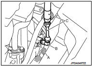
3. After warming up CVT, remove the oil pressure detection plug and install the joint pipe adapter (SST: KV31103600) (A), adapter (SST: 25054000) (B), oil pressure gauge set (commercial service tool) (C).
CAUTION:
When using the oil pressure gauge, be sure to use the Oring
attached to the oil pressure detection plug.
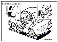
4. Securely engage the parking brake so that the tires do not turn.
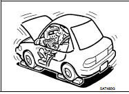
5. Start the engine, and then measure the line pressure at both idle and the stall speed.
CAUTION:
• Keep the brake pedal pressed all the way down during
measurement.
• When measuring the line pressure at the stall speed, refer to TM-186, "Inspection and Judgment".
6. After the measurements are complete, install the oil pressure detection plug and tighten to the specified torque below.
 : 7.5 N·m (0.77 kg-m, 66 in-lb)
CAUTION:
• Never reuse O-ring.
• Apply CVT fluid to O-ring.
Line Pressure
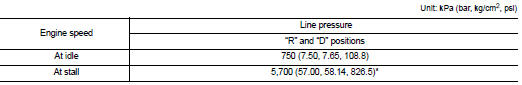
*: Reference values
JUDGMENT
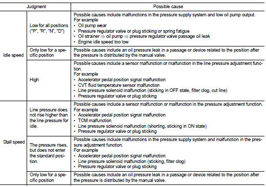
 Stall test
Inspection and Judgment
INSPECTION
1. Inspect the amount of engine oil. Replenish the engine oil if necessary.
2. Drive for about 10 minutes to warm up the vehicle so that the
CVT fluid temperatur ...
 Road test
Description
DESCRIPTION
• The purpose of the test is to determine overall performance of CVT
and analyze causes of problems.
• The road test consists of the following three parts:
1. “Check ...
Other materials:
Intelligent Blind Spot Intervention (I-BSI)
WARNING
Failure to strictly adhere to these safety warnings and operational instructions for the Intelligent Blind Spot Intervention (I-BSI) system could result in unpredictable vehicle behavior, potentially leading to serious personal injury or fatal accidents.
The I-BSI system ...
Front drive shaft boot
Exploded View
LEFT SIDE
1. Circular clip
2. Dust shield
3. Housing assembly
4. Boot band
5. Boot
6. Damper band
7. Dynamic damper
8. Circular clip
9. Joint sub-assembly
: Wheel side
: Fill NISSAN Genuine grease or
equivalent.
: Always replace after every
disassembly.
RIGHT ...
Inside mirror
Adjust the angle of the inside mirror to the desired position.
The night position1 will reduce glare from the headlights of vehicles behind
you at night.
Use the day position2 when driving in daylight hours.
WARNING
Use the night position only when necessary, because it reduces rear view c ...
