Nissan Juke Service and Repair Manual : Stall test
Inspection and Judgment
INSPECTION
1. Inspect the amount of engine oil. Replenish the engine oil if necessary.
2. Drive for about 10 minutes to warm up the vehicle so that the CVT fluid temperature is 50 to 80°C (122 to 176°F). Inspect the amount of CVT fluid. Replenish if necessary.
3. Securely engage the parking brake so that the tires do not turn.
4. Install a tachometer where it can be seen by driver during test.
NOTE
:
It is good practice to mark the point of specified engine rpm on
indicator.
5. Start engine, apply foot brake, and place selector lever in “D” position.
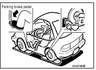
6. While holding down the foot brake, gradually press down the accelerator pedal.
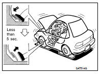
7. Quickly read off the stall speed, and then quickly remove your foot from the accelerator pedal.
CAUTION:
Never hold down the accelerator pedal for more than 5 seconds
during this test.
Stall speed: Refer to TM-308, "Stall Speed".
8. Move the selector lever to the “N” position.
9. Cool down the CVT fluid.
CAUTION:
Run the engine at idle for at least 1 minute.
10. Repeat steps 6 through 9 with selector lever in “R” position.
JUDGMENT
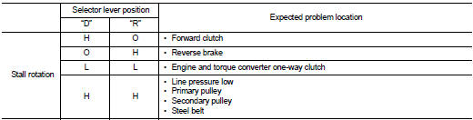
O: Stall speed within standard value position.
H: Stall speed is higher than standard value.
L: Stall speed is lower than standard value.
 CVT fluid
Inspection
CHECKING CVT FLUID
The fluid level should be checked with the fluid warmed up to 50 to 80°C (122
to 176°F). The fluid level check
procedure is as follows:
1. Check for fluid leakage ...
 Line pressure test
Inspection and Judgment
INSPECTION
Line Pressure Test Port
Line Pressure Test Procedure
1. Inspect the amount of engine oil and replenish if necessary.
2. Drive the car for about 10 minutes to ...
Other materials:
Warning information displays (models with a navigation system)
Low battery warning
When the low battery charge indicator
and the master warning light (yellow)
illuminate, the Nissan Leaf navigation system automatically triggers an alert on the display screen to notify the driver that the high-voltage Li-ion battery ...
Before starting the engine
• Make sure the area around the vehicle is clear.
• Check fluid levels such as engine oil, coolant, brake fluid, and window washer
fluid as frequently as
possible, or at least whenever you refuel.
• Check that all windows and lights are clean.
• Visually inspect tires for their appear ...
PC415 communication circuit
Description
CAN (Controller Area Network) is a serial communication line for real time
application. It is an on-vehicle multiplex
communication line with high data communication speed and excellent error
detection ability. Many electronic
control units are equipped onto a vehicle, and each co ...
