Nissan Juke Service and Repair Manual : Keyfob battery
Exploded View
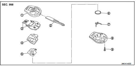
1. Upper case
2. Key
3. Switch cover
4. Switch rubber
5. Board surface
6. Battery
7. plate
8. Lower case
9. Screw
Removal and Installation
REMOVAL
1. Remove screw (9) on the rear of keyfob.
2. Place the key with the lower case (8) facing up. Set a screw-driver wrapped with tape between upper case (1) and lower case (8) and then separate the lower case (8) from the upper case (1).
CAUTION:
• Do not touch the circuit board or battery terminal.
• The keyfob is water-resistant. However, if it does get wet, immediately wipe it dry.
3. When replacing the circuit board assembly, remove circuit board assembly from the upper case (1).
[Circuit board assembly: Switch rubber (4) + Board surface (5)]
CAUTION:
Do not touch the printed circuits directly.
4. Remove the battery (6) from the lower case (8) and replace it.
Battery replacement : Coin-type lithium battery (CR1620)
CAUTION:
When replacing battery, keep dirt, grease, and other foreign materials off the
electrode contact
area.
5. After replacement, fit the lower and upper cases together, part (4), (7) and tighten with the screw.
CAUTION:
After replacing the battery, Be sure to check that door locking operates
normally using the keyfob.
Refer to DLK-528, "Component Function Check".
INSTALLATION
Install in the reverse order of removal.
 Remote keyless entry receiver
Removal and Installation
REMOVAL
1. Remove the glove box assembly. Refer to IP-13, "Removal and
Installation".
2. Remove the remote keyless entry receiver (1) mounting bolt (A),
and th ...

Other materials:
B1058, B1059, B1060, B1061, B1062, B1063 diagnosis sensor unit
DTC Logic
DTC DETECTION LOGIC
DTC CONFIRMATION PROCEDURE
1.CHECK SELF-DIAG RESULT
With CONSULT-III
1. Turn ignition switch ON.
2. Perform “Self Diagnostic Result” mode of “AIR BAG” using CONSULT-III.
Without CONSULT-III
1. Turn ignition switch ON.
2. Check the air bag warning la ...
Clutch piping
Exploded View
RS5F92R
1. CSC (Concentric Slave Cylinder)
2. Clutch tube
3. Clutch damper
4. Bracket
5. Master cylinder
RS6F94R
1. CSC (Concentric Slave Cylinder)
2. Clutch tube
3. Clutch damper
4. Bracket
5. Master cylinder
Hydraulic Layout
1. Clutch tube
2. Lock pin
3. ...
Regulatory information
Bluetooth trademark:
Bluetooth® is a trademark owned by Bluetooth SIG, Inc., and licensed to Visteon
Corporation.
FCC Regulatory information
• CAUTION: To maintain compliance with FCC’s RF exposure guidelines, use only
the supplied antenna. Unauthorized antenna, modification, or attach ...
