Nissan Juke Service and Repair Manual : Key switch
Component Function Check
1.CHECK FUNCTION
1. Select “DOOR LOCK” of “BCM” using CONSULT-III.
2. Select “KEY ON SW” in “DATA MONITOR” mode.
3. Check that the function operates normally according to the following conditions.
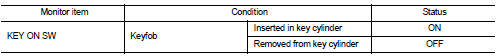
Is the inspection result normal? YES >> Key switch is OK.
NO >> Refer to DLK-526, "Diagnosis Procedure".
Diagnosis Procedure
1.CHECK FUSE
1. Turn ignition switch OFF.
2. Check 10 A fuse, [No.7, located in fuse block (J/B)].
Is fuse fusing? YES >> Replace the blown fuse after repairing the affected circuit if a fuse is blown.
NO >> GO TO 2.
2.CHECK KEY SWITCH POWER SUPPLY CIRCUIT
1. Disconnect key switch connector.
2. Check voltage between key switch harness connector and ground.
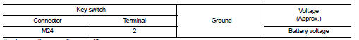
Is the inspection result normal? YES >> GO TO 3.
NO >> Repair or replace harness.
3.CHECK KEY SWITCH CIRCUIT
1. Disconnect BCM connector.
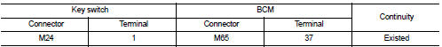
2. Check continuity between key switch harness connector and BCM harness connector.
3. Check continuity between key switch connector and ground.
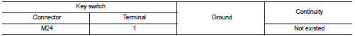
Is the inspection result normal? YES >> GO TO 4 NO >> Repair or replace harness.
4.CHECK KEY SWITCH
Refer to DLK-527, "Component Inspection".
Is the inspection result normal? YES >> GO TO 5.
NO >> Replace key switch.
5.CHECK INTERMITTENT INCIDENT
Refer to GI-42, "Intermittent Incident".
>> INSPECTION END
Component Inspection
COMPONENT INSPECTION
1.CHECK KEY SWITCH
1. Turn ignition switch OFF.
2. Disconnect key switch connector.
3. Check continuity between key switch terminals.
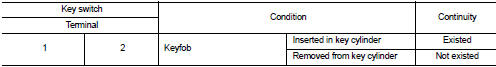
Is the inspection result normal? YES >> INSPECTION END
NO >> Replace key switch.
 Hazard function
Component Function Check
1.CHECK FUNCTION
1. Select “MULTI REMOTE ENT” of “BCM” using CONSULT-III.
2. Select “FLASHER” in “ACTIVE TEST” mode.
3. Check that the function operates no ...
 Keyfob battery
Component Function Check
1.CHECK FUNCTION
Check door lock and unlock operation with keyfob button.
Is the inspection result normal?
YES >> Keyfob is OK.
NO >> Refer to DLK-528, &q ...
Other materials:
Electric ignition system
Electric ignition system : System Diagram
Electric ignition system : System Description
INPUT/OUTPUT SIGNAL CHART
*1: CVT models
*2: M/T models
*3: ECM determines the start signal status by the signals of engine speed and
battery voltage.
SYSTEM DESCRIPTION
Firing order: 1 ...
Wiring diagram
ELECTRONICALLY CONTROLLED POWER STEERING SYSTEM
Wiring Diagram
For connector terminal arrangements, harness layouts, and alphabets in a
(option abbreviation; if not
described in wiring diagram), refer to GI-12, "Connector Information/Explanation
of Option Abbreviation".
...
Oil pressure switch signal circuit
Component Function Check
1.CHECK COMBINATION METER INPUT SIGNAL
Select the “Data Monitor” for the “METER/M&A” and check the “OIL W/L” monitor
value.
“OIL W/L”
Ignition switch ON : On
Engine running : Off
>> INSPECTION END
Diagnosis Procedure
1.CHECK OIL PRESSURE S ...
