Nissan Juke Service and Repair Manual : Hood switch
Component Function Check
1.CHECK FUNCTION
1. Select “HOOD SW” in “Data Monitor” mode of “IPDM E/R” using CONSULT-III.
2. Check “HOOD SW” indication under the following condition.
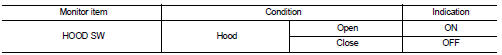
Is the indication normal? YES >> Hood switch is OK.
NO >> Go to SEC-223, "Diagnosis Procedure".
Diagnosis Procedure
1.CHECK HOOD SWITCH SIGNAL CIRCUIT 1
1. Turn ignition switch OFF.
2. Disconnect hood switch connector.
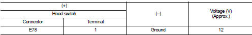
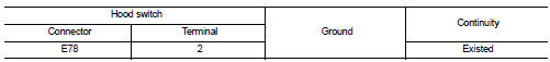
3. Check voltage between hood switch harness connector and ground.
Is the inspection result normal? YES >> GO TO 3.
NO >> GO TO 2.
2.CHECK HOOD SWITCH SIGNAL CIRCUIT 2
1. Disconnect IPDM E/R connector.
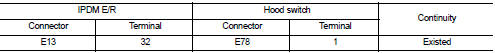
2. Check continuity between IPDM E/R harness connector and hood switch harness connector.
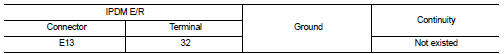
3. Check continuity between IPDM E/R harness connector and ground.
Is the inspection result normal? YES >> Replace IPDM E/R. Refer to PCS-63, "Removal and Installation".
NO >> Repair or replace harness.
3.CHECK HOOD SWITCH GROUND CIRCUIT
Check continuity between hood switch harness connector and ground.
Is the inspection result normal? YES >> GO TO 4.
NO >> Repair or replace harness.
4.CHECK HOOD SWITCH
Refer to SEC-224, "Component Inspection".
Is the inspection result normal? YES >> GO TO 5.
NO >> Replace hood switch.
5.CHECK INTERMITTENT INCIDENT
Refer to GI-42, "Intermittent Incident".
>> INSPECTION END
Component Inspection
1.CHECK HOOD SWITCH
1. Turn ignition switch OFF.
2. Disconnect hood switch connector.
3. Check continuity between hood switch terminals.
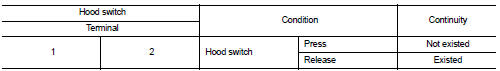
Is the inspection result normal? YES >> INSPECTION END
NO >> Replace hood switch.
 B210E starter relay
DTC Logic
DTC DETECTION LOGIC
NOTE:
• If DTC B210E is displayed with DTC U1000, first perform the trouble diagnosis
for DTC U1000. Refer to
PCS-59, "DTC Logic".
• If DTC B210E is ...
 Horn function
Component Function Check
1.CHECK FUNCTION 1
1. Disconnect vehicle security horn relay.
2. Perform “VEHICLE SECURITY HORN” in “ACTIVE TEST” mode of “THEFT ALM” of “BCM”
using CONSU ...
Other materials:
4WD mode indicator lamp (4WD)
Component Function Check
1.4WD MODE INDICATOR LAMP OPERATION CHECK
Check that 4WD mode indicator lamp (4WD) turns on for approximately 1 second
after the ignition switch is
turned ON.
Is the inspection result normal?
YES >> INSPECTION END
NO >> Proceed to diagnosis procedure. R ...
Hood switch
Component Function Check
1.CHECK FUNCTION
1. Select “HOOD SW” in “Data Monitor” mode of “IPDM E/R” using CONSULT-III.
2. Check “HOOD SW” indication under the following condition.
Is the indication normal?
YES >> Hood switch is OK.
NO >> Go to SEC-155, "Diag ...
If the Li-ion battery becomes completely discharged
Should the power limitation indicator light
illuminate while you are driving your Nissan Leaf, be aware that the system has restricted the output of the traction motor. This is an intentional safety feature designed to preserve remaining energy, and you will notice a correspondin ...
