Nissan Juke Service and Repair Manual : U1000 can comm circuit
Description
CAN (Controller Area Network) is a serial communication line for real time applications. It is an on-board multiplex communication line with high data communication speed and excellent error detection ability. A modern vehicle is equipped with many ECMs, and each control unit shares information and links with other control units during operation (not independent). In CAN communication, 2 control units are connected with 2 communication lines (CAN-L line and CAN-H line) allowing a high rate of information transmission with less wiring.
Each control unit transmits/receives data but selectively reads required data only.
Refer to LAN-31, "CAN COMMUNICATION SYSTEM : CAN Communication Signal Chart" for details of the communication signal.
DTC Logi
DTC DETECTION LOGIC
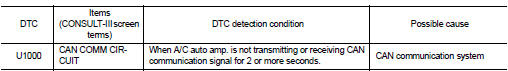
DTC CONFIRMATION PROCEDURE
1.PERFORM DTC CONFIRMATION PROCEDURE
 With CONSULT-III
1. Turn ignition switch ON and wait at least 2 seconds or more.
2. Select ŌĆ£Self Diagnostic ResultŌĆØ mode of ŌĆ£HVACŌĆØ using CONSULT-III.
3. Check DTC.
Is DTC detected? YES >> Refer to HAC-51, "Diagnosis Procedure".
NO >> Check intermittent incident. Refer to GI-42, "Intermittent Incident".
Diagnosis Procedure
1.CHECK CAN COMMUNICATION SYSTEM
Check CAN communication system. Refer to LAN-17, "Trouble Diagnosis Flow Chart".
>> INSPECTION END

 U1010 control unit (CAN)
Description
Initial diagnosis of A/C auto amp.
DTC Logic
DTC DETECTION LOGIC
DTC CONFIRMATION PROCEDURE
1.PERFORM DTC CONFIRMATION PROCEDURE
With CONSULT-III
1. Turn ignition switch ON.
2. S ...
Other materials:
Wiring diagram
DOOR & LOCK SYSTEM
Wiring Diagram
For connector terminal arrangements, harness layouts, and alphabets in a
(option abbreviation; if not
described in wiring diagram), refer to GI-12, "Connector Information/Explanation
of Option Abbreviation".
...
Brake pedal
Inspection and Adjustment
INSPECTION
Brake Pedal Height
Check the height (H1) between the dash lower panel (1) and the
brake pedal upper surface.
H1 : Refer to BR-70, "Brake Pedal".
CAUTION:
Remove the floor trim.
Stop Lamp Switch
Check the clearance (C) among the brake pedal le ...
Back door
Exploded View
REMOVAL
1. Back door weather-strip
2. Back door stay
3. Back door stay lower bracket
4. Bumper rubber
5. Back door striker
6. Back door panel
7. Back door hinge
8. Hole cover
A : Center mark
B : Seam
: Do not reuse
: Body grease
Back door assembly
BACK DOOR ASSEMB ...
