Nissan Juke Service and Repair Manual : Hood
Exploded View
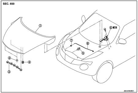
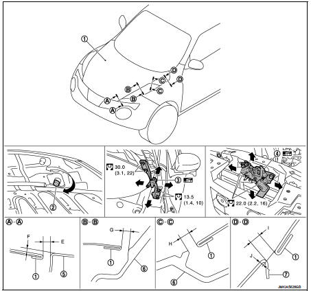
1. Hood assembly
2. Hood bumper rubber
3. Radiator core seal
4. Hood bumper rubber
5. Clamp
6. Hood hinge
7. Grommet
8. Hood support rod
 : Clip
 : Pawl
 : Body grease
Hood assembly
HOOD ASSEMBLY : Removal and Installation
CAUTION:
• Operate with two workers, because of its heavy weight.
• Use protective tape or shop cloth to protect from damage during removal and installation.
REMOVAL
1. Support hood assembly with the proper material to prevent it from falling.
WARNING:
Injury may occur if hood assembly is not supported by the proper material when
removing hood
assembly.
2. Remove hood hinge mounting nuts on the hood to remove the hood assembly.
INSTALLATION
Note the following items, and then install in the reverse order of removal.
CAUTION
:
• After installation, apply touch-up paint (the body color) onto the heads of
hood hinge mounting bolts
and nuts.
• After installing, perform hood fitting adjustment. Refer to DLK-440, "HOOD ASSEMBLY : Adjustment".
HOOD ASSEMBLY : Adjustment
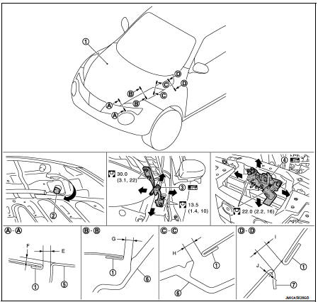
1. Hood assembly
2. Hood bumper rubber
3. Hood hinge
4. Hood lock assembly
5. Front bumper fascia
6. Front combination lamp
7. Front fender
 : N·m (kg-m, ft-lb)
 : Body grease
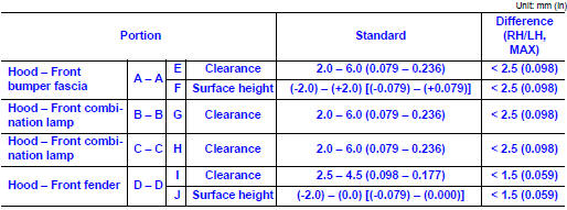
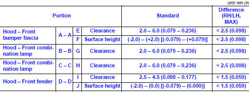
Check the clearance and the surface height between hood and each part by visually and touching.
If the clearance and the surface height are out of specification, adjust them according to the procedures shown below.
FITTING ADJUSTMENT PROCEDURE
1. Remove front center grille. Refer to EXT-18, "Removal and Installation".
2. Remove hood lock assembly, and then adjust the surface height of hood assembly, front fender assembly, and front combination lamp according to the specified value, by rotating hood bumper rubber.
3. Position hood lock assembly and engage hood striker. Check hood lock assembly and hood striker for looseness.
4. Move hood lock assembly laterally until the center of hood striker and hood lock assembly are vertical when viewed from the front.
5. After adjustment, tighten lock bolts to the specified torque.
6. Open hood. Rotate bumper rubber counterclockwise between half a turn and three-quarters of a turn.
7. Check that secondary latch is securely engaged with secondary hood striker from the dead load of the hood assembly.
8. Check that primary latch is securely engaged with primary hood striker when hood assembly is closed [free-fall from approximately 200 mm (7.874 in) height].
CAUTION:
Never free-fall hood assembly from a height of 300 (11.811 in) mm or more.
9. Install front center grille. Refer to EXT-18, "Removal and Installation".
Hood hinge
HOOD HINGE : Removal and Installation
REMOVAL
1. Remove hood assembly. Refer to DLK-439, "HOOD ASSEMBLY : Removal and Installation".
2. Remove front fender. Refer to DLK-450, "Removal and Installation".
3. Remove hood hinge mounting bolts, and then remove hood hinge.
INSTALLATION
Note the following items, and then install in the reverse order of removal.
CAUTION:
• After installation, perform hood hinge fitting adjustment. Refer to DLK-442,
"HOOD HINGE : Adjustment".
• After installation, apply touch-up paint (the body color) onto the head of the hinge mounting bolts and nuts.
• Check hood hinge rotating part for poor lubrication. If necessary, apply grease.
HOOD HINGE : Adjustment
1. Hood assembly
2. Hood bumper rubber
3. Hood hinge
4. Hood lock assembly
5. Front bumper fascia
6. Front combination lamp
7. Front fender
 : N·m (kg-m, ft-lb)
 : Body grease
Check the clearance and the surface height between hood and each part by visually and touching
If the clearance and the surface height are out of specification, adjust them according to the procedures shown below.
1. Remove front center grille. Refer to EXT-18, "Removal and Installation".
2. Remove hood lock assembly.
3. Remove front bumper fascia. Refer to EXT-13, "Removal and Installation".
4. Remove front combination lamp (LH and RH). Refer to EXL-91, "Removal and Installation".
5. Remove front fender assembly (LH and RH). Refer to DLK-450, "Removal and Installation".
6. Loosen hood hinge mounting bolts.
7. Temporarily install front fender assembly (LH and RH), front combination lamp (LH and RH) and front bumper fascia.
8. Adjust the clearance of hood assembly, front fender assembly (LH and RH), front combination lamp (LH and RH) and front bumper fascia according to the specified value, by moving hood hinge (body side).
9. Temporarily tighten hood hinge (LH and RH).
10. Remove front bumper fascia, front combination lamp (LH and RH) and front fender assembly (LH and RH).
11. Tighten hood hinge (LH and RH) to the specified torque.
12. Install front fender assembly (LH and RH). Refer to DLK-450, "Removal and Installation".
13. Install front combination lamp (LH and RH). Refer to EXL-91, "Removal and Installation".
14. Install front bumper fascia. Refer to EXT-13, "Removal and Installation".
15. Adjust the surface height of hood assembly, front fender assembly, and front combination lamp according to the specified value, by rotating hood bumper rubber.
16. Position hood lock assembly and engage hood striker. Check hood lock assembly and hood striker for looseness.
17. Move hood lock assembly laterally until the center of hood striker and hood lock assembly are vertical when viewed from the front.
18. After adjustment, tighten lock bolts to the specified torque.
19. Open hood. Rotate bumper rubber counterclockwise between half a turn and three-quarters of a turn.
20. Check that secondary latch is securely engaged with secondary hood striker from the dead load of the hood assembly.
21. Check that primary latch is securely engaged with primary hood striker when hood assembly is closed [free-fall from approximately 200 mm (7.874 in) height].
CAUTION:
Never free-fall hood assembly from a height of 300 (11.811 in) mm or more
.
22. Install front center grille. Refer to EXT-18, "Removal and Installation".
CAUTION:
After installation, apply touch-up paint (the body color) onto the heads of hood
hinge mounting
bolts and nuts.
Hood support rod
HOOD SUPPORT ROD : Removal and Installation
REMOVAL
CAUTION:
Two workers are required to support the hood.
1. Support hood assembly with a suitable material to prevent it from falling.
WARNING:
Injury may occur if hood assembly is not supported by the proper material when
removing hood
assembly.
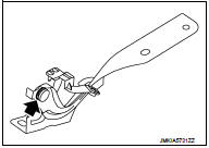
2. Pull hood support rod from grommet and remove.
INSTALLATION
Install in the reverse order of removal.

 Radiator core support
HR16DE
HR16DE : Exploded View
1. Radiator core support upper
2. Air guide RH (MT models)
3. Radiator core support lower
4. Air guide LH
5. Air guide (upper)
6. Air guide LH (CVT models)
...
Other materials:
U1000 can comm circuit
Description
CAN (Controller Area Network) is a serial communication line for real time
applications. It is an on-board multiplex
communication line with high data communication speed and excellent error
detection ability. A modern
vehicle is equipped with many ECMs, and each control unit shar ...
P range interlock door lock/unlock function does not operate
Diagnosis Procedure
1.CHECK “AUTOMATIC LOCK/UNLOCK SELECT” SETTING IN “WORK SUPPORT”
1. Select “DOOR LOCK” of “BCM” using CONSULT-III.
2. Select “AUTOMATIC LOCK/UNLOCK SELECT” in “WORK SUPPORT” mode.
3. Check “AUTOMATIC LOCK/UNLOCK SELECT” in “WORK SUPPORT”.
Re ...
Refilling
1. Remove filler plug (1) and gasket from transaxle case.
2. Fill with new gear oil until oil level reaches the specified limit at
filler plug mounting hole as shown in the figure.
Oil grade and
viscosity
: Refer to MA-13, "Fluids and Lubricants".
Oil capacity : Refer to TM-63, " ...
