Nissan Juke Service and Repair Manual : General Precautions
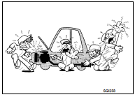
• Do not operate the engine for an extended period of time without proper exhaust ventilation.
Keep the work area well ventilated and free of any inflammable materials. Special care should be taken when handling any inflammable or poisonous materials, such as gasoline, refrigerant gas, etc. When working in a pit or other enclosed area, be sure to properly ventilate the area before working with hazardous materials.
Do not smoke while working on the vehicle.

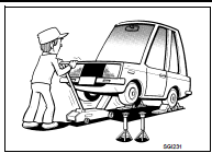
• Before jacking up the vehicle, apply wheel chocks or other tire blocks to the wheels to prevent the vehicle from moving. After jacking up the vehicle, support the vehicle weight with safety stands at the points designated for proper lifting before working on the vehicle.
These operations should be done on a level surface.
• When removing a heavy component such as the engine or transaxle/ transmission, be careful not to lose your balance and drop them. Also, do not allow them to strike adjacent parts, especially the brake tubes and master cylinder.

• Before starting repairs which do not require battery power: Turn off ignition switch. Disconnect the negative battery terminal.
• If the battery terminals are disconnected, recorded memory of radio and each control unit is erased.

• To prevent serious burns: Avoid contact with hot metal parts. Do not remove the radiator cap when the engine is hot.
• Dispose of drained oil or the solvent used for cleaning parts in an appropriate manner.
• Do not attempt to top off the fuel tank after the fuel pump nozzle shuts off automatically.
Continued refueling may cause fuel overflow, resulting in fuel spray and possibly a fire.
• Clean all disassembled parts in the designated liquid or solvent prior to inspection or assembly.
• Replace oil seals, gaskets, packings, O-rings, locking washers, cotter pins, self-locking nuts, etc. with new ones.
• Replace inner and outer races of tapered roller bearings and needle bearings as a set.
• Arrange the disassembled parts in accordance with their assembled locations and sequence.
• Do not touch the terminals of electrical components which use microcomputers (such as ECM). Static electricity may damage internal electronic components.
• After disconnecting vacuum or air hoses, attach a tag to indicate the proper connection.
• Use only the fluids and lubricants specified in this manual.
• Use approved bonding agent, sealants or their equivalents when required.
• Use hand tools, power tools (disassembly only) and recommended special tools where specified for safe and efficient service repairs.
• When repairing the fuel, oil, water, vacuum or exhaust systems, check all affected lines for leakage.


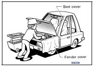
• Before servicing the vehicle: Protect fenders, upholstery and carpeting with appropriate covers.
Take caution that keys, buckles or buttons do not scratch paint.

WARNING:
To prevent ECM from storing the diagnostic trouble codes, never carelessly
disconnect the harness
connectors which are related to the engine control system and TCM (transmission
control module)
system. The connectors should be disconnected only when working according to the
WORK FLOW of
TROUBLE DIAGNOSES in EC and TM sections.
 Precaution for Procedure without Cowl Top Cover
When performing the procedure after removing cowl top cover, cover
the lower end of windshield with urethane, etc.
...
 Three Way Catalyst
If a large amount of unburned fuel flows into the catalyst, the catalyst
temperature will be excessively high. To
prevent this, follow the instructions.
• Use unleaded gasoline only. Leaded gaso ...
Other materials:
EPS branch line circuit
Diagnosis Procedure
1.CHECK CONNECTOR
1. Turn the ignition switch OFF.
2. Disconnect the battery cable from the negative terminal.
3. Check the terminals and connectors of the EPS control unit for damage, bend
and loose connection (unit
side and connector side).
Is the inspection result no ...
Front fog lamp circuit
Component Function Check
1.CHECK FRONT FOG LAMP OPERATION
CONSULT-III ACTIVE TEST
1. Select “EXTERNAL LAMPS” of IPDM E/R active test item.
2. With operating the test items, check that the front fog lamp is turned ON.
Fog : Front fog lamp ON
Off : Front fog lamp OFF
Is the measurement normal?
...
On board diagnostic (OBD) system
Diagnosis Description
This system is an on board diagnostic system that records exhaust
emission-related diagnostic information
and detects a sensors/actuator-related malfunction. A malfunction is indicated
by the malfunction indicator
lamp (MIL) and stored in ECU memory as a DTC. The diagnos ...
