Nissan Juke Service and Repair Manual : Front fog lamp
Exploded View
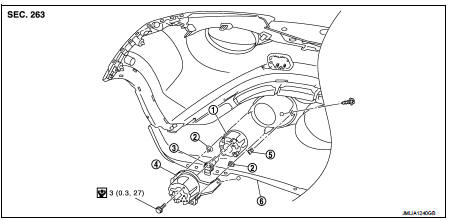
1. Front fog lamp assembly
2. Metal clip
3. Front fog lamp bulb
4. Front fog lamp bracket
5. U nut
6. Front bumper fascia lower
 : Pawl
 : N·m (kg-m, in-lb)
Removal and Installation
CAUTION:
Disconnect the battery negative terminal or remove the fuse.
REMOVAL
1. Remove front fender protector. Keep the service area. Refer to EXT-22, "Removal and Installation".
2. Disconnect front fog lamp harness connector.
3. Remove front fog lamp bracket.
4. Remove front fog lamp mounting bolt, and then remove front fog lamp from front fog lamp bracket.
INSTALLATION
Note the following item, and then installation is the reverse order of removal.
NOTE
:
After installation, perform aiming adjustment. Refer to EXL-88, "Description"
Replacement
CAUTION:
• Disconnect the battery negative terminal or remove the fuse.
• Never touch the glass of bulb directly by hand. Keep grease and other oily matters awy from it.
• Never touch bulb by hand while it is lit or right after being turned off.
• Never leave bulb out of lamp reflector for a long time because dust, moisture smoke, etc. may affect the performance of lamp. When replacing bulb, be sure to replace it with new one.
FRONT FOG LAMP BULB
1. Remove fender protector. Keep the service area. Refer to EXT-22, "Removal and Installation".
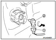
2. Remove front fog lamp bulb connector (1).
3. Rotate the bulb (2) counterclockwise and unlock it.
 Front combination lamp
Exploded View
REMOVAL
1. Front combination lamp
: N·m (kg-m, in-lb)
DISASSEMBLY
1. Parking lamp bulb
2. Parking lamp bulb socket
3. Front turn signal lamp bulb socket
4. Front turn sign ...
 Light & rain sensor
Exploded View
CAUTION:
When the light & rain sensor is removed from windshield, the light & rain sensor
cannot be re-used.
REMOVAL
1. Light & rain sensor bracket
2. Mirror base
...
Other materials:
P0201, P0202, P0203, P0204 fuel injector
DTC Logic
DTC DETECTION LOGIC
DTC CONFIRMATION PROCEDURE
1.PRECONDITIONING
If DTC Confirmation Procedure has been previously conducted, always perform
the following procedure
before conducting the next test.
1. Turn ignition switch OFF and wait at least 10 seconds.
2. Turn ignition swit ...
Diagnosis system (BCM)
Common item
COMMON ITEM : CONSULT-III Function (BCM - COMMON ITEM)
APPLICATION ITEM
CONSULT-III performs the following functions via CAN communication with BCM.
SYSTEM APPLICATION
BCM can perform the following functions for each system.
NOTE:
It can perform the diagnosis modes except the fo ...
B210F shift position/clutch interlock switch
DTC Logic
DTC DETECTION LOGIC
NOTE:
If DTC B210F is displayed with DTC U1000, first perform the trouble diagnosis
for DTC U1000. Refer to PCS-
30, "DTC Logic".
DTC CONFIRMATION PROCEDURE
1.PERFORM DTC CONFIRMATION PROCEDURE
1. Shift selector lever to the P position.
2. Turn ign ...
