Nissan Juke Service and Repair Manual : Flushing
1. Install radiator drain plug.
CAUTION:
Be sure to clean drain plug and install with new O-ring.
Radiator drain plug : Refer to CO-17, "Exploded View".
• If water drain plugs on cylinder block are removed, close and tighten them. Refer to EM-63, "Setting".
2. Remove air duct (between air cleaner cover assembly and turbocharger), air cleaner cover assembly and air cleaner body assembly. Refer to EM-26, "Exploded View".
3. Disconnect vacuum hose break booster side, and remove vacuum tube from clamp. Refer to .
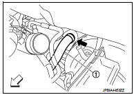
4. Disconnect heater hose (1) at position ( ) in the figure.
 : Vehicle front
• Enhance heater as high as possible.
5. Fill radiator and reservoir tank with water and reinstall radiator cap.
• When engine coolant over flows disconnected heater hose, connect heater hose, and continue filling the engine coolant.
6. Connect vacuum hose, and install vacuum tube. Refer to .
7. Install air duct (between air cleaner cover and turbocharger), air cleaner cover assembly and air cleaner body assembly. Refer to EM-26, "Exploded View".
8. Run the engine and warm it up to normal operating temperature.
9. Rev the engine two or three times under no-load.
10. Stop the engine and wait until it cools down.
11. Drain water from the system. Refer to CO-11, "Draining".
12. Repeat steps 1 through 9 until clear water begins to drain from radiator.
 Refilling
1. IInstall reservoir tank if removed, and install radiator drain plug.
CAUTION:
Be sure to clean drain plug and install with new O-ring.
Radiator drain plug : Refer to CO-17, "Exploded View ...
 Radiator
RADIATOR CAP ...
Other materials:
Sealant or/and Lubricant
HFC-134a (R-134a) Service Tool and Equipment
• Never mix HFC-134a (R-134a) refrigerant and/or its specified lubricant with
CFC-12 (R-12) refrigerant and/
or its lubricant.
• Separate and non-interchangeable service equipment must be used for handling
each type of refrigerant/
lubricant.
...
How to set srt code
Description
OUTLINE
In order to set all SRTs, the self-diagnoses as in the “SRT ITEM” table must
have been performed at least
once. Each diagnosis may require actual driving for a long period of time under
various conditions.
SRT ITEM
The table below shows required self-diagnostic ite ...
B1129 side air bag module RH
DTC Logic
DTC DETECTION LOGIC
DTC CONFIRMATION PROCEDURE
1.CHECK SELF-DIAG RESULT
With CONSULT-III
1. Turn ignition switch ON.
2. Perform “Self Diagnostic Result” mode of “AIR BAG” using CONSULT-III.
Without CONSULT-III
1. Turn ignition switch ON.
2. Check the air bag warning la ...
