Nissan Juke Service and Repair Manual : Body construction
Body Construction (RHD Models)
1. Outer side body
2. Outer front pillar reinforcement
3. Upper inner front pillar
4. Lower dash
5. Hoodledge reinforcement
6. Lower front pillar hinge brace
7. Weld nut
8. Side dash
9. Upper hinge plate
10. Lower hinge plate
11. Inner front pillar reinforcement
12. Inner front sill reinforcement
13. Inner sill
14. Front floor reinforcement
15. Front floor
16. Front outrigger
17. Outer sill reinforcement
18. Plate nut
19. Inner center pillar
20. Center pillar reinforcement
21. Center pillar hinge brace
22. Center sill reinforcement
23. Inner sill extension
24. Inner rear wheelhouse
25. Outer rear wheelhouse
26. Rear roof rail brace
27. Inner rear pillar reinforcement
28. Rear fender extension
29. Inner rear pillar
30. Inner rear wheelhouse reinforcement
Body Construction (LHD Models)
1. Outer side body
2. Outer front pillar reinforcement
3. Upper inner front pillar
4. Lower dash
5. Hoodledge reinforcement
6. Lower front pillar hinge brace
7. Weld nut
8. Side dash
9. Upper hinge plate
10. Lower hinge plate
11. Inner front pillar reinforcement
12. Inner front sill reinforcement
13. Inner sill
14. Front floor reinforcement
15. Front floor
16. Front outrigger
17. Outer sill reinforcement
18. Plate nut
19. Inner center pillar
20. Center pillar reinforcement
21. Center pillar hinge brace
22. Center sill reinforcement
23. Inner sill extension
24. Inner rear wheelhouse
25. Outer rear wheelhouse
26. Rear roof rail brace
27. Inner rear pillar reinforcement
28. Rear fender extension
29. Inner rear pillar
30. Inner rear wheelhouse reinforcement
31. Upper inner front pillar reinforcement
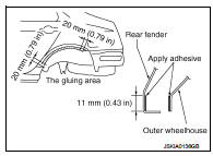
Rear Fender Hemming Process
1. A wheel arch is to be installed and hemmed over the left and right outer wheel houses.
2. In order to hem the wheel arch, it is necessary to repair any damaged or defaced parts around outer wheel house.
CAUTION:
Ensure that the area that is to be glued around the outer wheelhouse is
undamaged or defaced.
PROCEDURE OF THE HEMMING PROCESS
• Peel off old bonding material on the surface of the outer wheelhouse and clean thoroughly.
• Peel off a primer coat in the specified area where new adhesive is to be applied on rear fender (the replacing part).
• Apply new adhesive to both specified areas of the outer wheelhouse and rear fender.
<Adhesive> 3M™ Automix™ Panel Bonding Adhesive 08115 or equivalent
• Attach rear fender to the body of the car, and weld the required part except the hemming part.
• Bend the welded part starting from the center of the wheel arch
gradually with a hammer and a dolly. (Also hem the end of the
flange.)
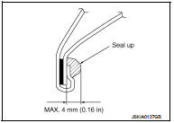
• Hemming with a hammer is conducted to an approximate angle of
80 degrees.
• Starting from the center, hem the wheel arch gradually, using slight back and forth motion with a hemming tool.
• Seal up the area around the hemmed end of the flange.
 Corrosion protection
Description
To provide improved corrosion prevention, the following anti-corrosive
measures have been implemented in
NISSAN production plants. When repairing or replacing body panels, it is
nece ...
 Replacement operations
Description
• This section is prepared for technicians who have attained a high level of
skill and experience in repairing
collision-damaged vehicles and also use modern service tools and equipm ...
Other materials:
Spark plug
Removal and Installation
REMOVAL
1. Remove ignition coil. Refer to EM-178, "Exploded View".
2. Remove spark plug with a spark plug wrench (commercial service
tool).
a : 14 mm (0.55 in)
CAUTION:
Never drop or shock spark plug.
INSTALLATION
Install in the reverse order of removal ...
Washer pump
Exploded View
1. Front washer nozzle LH
2. Front washer nozzle RH
3. Front washer tube LH
4. Front washer tube RH
5. Check valve
6. Front washer tube
7. Joint
8. Washer tank inlet cap
9. Washer tank inlet
10. Washer tank
11. Headlamp washer pump
12. Washer pump
13. Packing
1 ...
Condenser
Exploded View
Refer toINT-34, "Exploded View"
Removal and Installation
REMOVAL
1. Remove the back door lower finisher.
Refer to INT-35, "BACK DOOR LOWER FINISHER : Removal and Installation"
2. Remove bolt (A), and then remove condenser (1) from the vehicle
body.
INSTA ...
