Nissan Juke Service and Repair Manual : Evaporative emission system
Inspection
1. Visually inspect EVAP vapor lines for improper attachment and for cracks, damage, loose connections, chafing and deterioration.
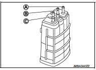
2. Check EVAP canister as follows: a. Block port (A). Orally blow air through port (B).
Check that air flows freely through port (C).
b. Block port (B). Orally blow air through port (A).
Check that air flows freely through port (C).
3. Visually inspect the fuel check valve for cracks, damage, loose connections chafing and deterioration.
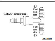
4. Check fuel check valve as follows: a. Blow air through connector on the fuel tank side. A considerable resistance should be felt and a portion of air flow should be directed toward the EVAP canister side.
b. Blow air through connector on EVAP canister side. Air flow should be smoothly directed toward fuel tank side.
c. If fuel check valve is suspected or not properly functioning in step 1 and 2 above, replace it.
5. Inspect fuel tank filler cap vacuum relief valve for clogging, sticking, etc.
a. Wipe clean valve housing.
b. Check valve opening pressure and vacuum.
Pressure:
15.3 - 20.0 kPa (0.153 - 0.200 bar, 0.156 - 0.204 kg/
cm2, 2.22 - 2.90 psi)
Vacuum:
–6.0 to –3.4 kPa (–0.06 bar to –-0.034bar, –0.061 to –
0.035 kg/cm2, –0.87 to –0.49 psi)
c. If out of specification, replace fuel filler cap as an assembl
 Ignition timing
Inspection
1.CHECK IGNITION TIMING
1. Attach timing light to loop wire as shown.
1. Loop wire
A. Timing light
B. Timing indicator
2. Check ignition timing.
>> INSPECTION END ...
 Positive crankcase ventilation
Inspection
1.CHECK PCV VALVE
With engine running at idle, remove PCV valve from rocker cover. A
properly working valve makes a hissing noise as air passes through
it. A strong vacuum should be fel ...
Other materials:
Option harness
Wiring Diagram
For connector terminal arrangements, harness layouts, and alphabets in a
(option abbreviation; if not
described in wiring diagram), refer to GI-12, "Connector Information/Explanation
of Option Abbreviation".
...
Operation
Autmatic speed control device (ASCD) : Switch Name and Function
SWITCHES AND INDICATORS
NOTE:
Shared with speed limiter switch.
1. CRUISE indicator lamp
2. SET indicator lamp
3. CANCEL switch
4. Speed limiter MAIN switch
5. ASCD MAIN switch
6. SET / − switch
(SET / COAST)
7. ...
C1164, C1165 CV system
DTC Logic
DTC DETECTION LOGIC
DTC CONFIRMATION PROCEDURE
1.PRECONDITIONING
If “DTC CONFIRMATION PROCEDURE” has been previously conducted, always turn
ignition switch OFF and
wait at least 10 seconds before conducting the next test.
>> GO TO 2.
2.CHECK DTC DETECTION
With CON ...
