Nissan Juke Service and Repair Manual : B1023 passenger air bag off indicator
DTC Logic
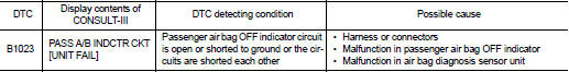
DTC DETECTION LOGIC
DTC CONFIRMATION PROCEDURE
1.CHECK SELF-DIAG RESULT
 With CONSULT-III
1. Turn ignition switch ON.
2. Perform ŌĆ£Self Diagnostic ResultŌĆØ mode of ŌĆ£AIR BAGŌĆØ using CONSULT-III.
 Without CONSULT-III
1. Turn ignition switch ON.
2. Check the air bag warning lamp status. Refer to SRC-12, "On Board Diagnosis Function".
NOTE
:
SRS does not enter the diagnosis mode if no malfunction is detected in the user
mode.
Is malfunctioning part detected? YES >> Refer to SRC-32, "Diagnosis Procedure".
NO >> INSPECTION EN
Diagnosis Procedure
WARNING:
ŌĆó Before servicing, turn ignition switch OFF, disconnect battery negative
terminal, and wait 3 minutes
or more. (To discharge backup capacitor.)
ŌĆó Never use unspecified tester or other measuring device.
DIAGNOSTIC PROCEDURE
1.CHECK HARNESS CONNECTOR
Check the connection of harness connector.
Is the inspection result normal? YES >> GO TO 2.
NO >> Replace harness connectors.
2.CHECK WIRING HARNESS
Check the wiring harness externals.
Is the inspection result normal? YES >> GO TO 3.
NO >> Replace wiring harness.
3.CHECK PASSENGER AIR BAG OFF INDICATOR
1. Replace passenger air bag OFF indicator.
2. Perform DTC confirmation procedure. Refer to SRC-32, "DTC Logic".
Is DTC detected? YES >> GO TO 4.
NO >> INSPECTION END
4.REPLACE AIR BAG DIAGNOSIS SENSOR UNIT
1. Replace air bag diagnosis sensor unit. Refer to SR-30, "Removal and Installation".
2. Perform DTC confirmation procedure. Refer to SRC-32, "DTC Logic".
Is DTC detected? YES >> GO TO 1.
NO >> INSPECTION END
 B1011, B1012, B1013, B1014, B1015 diagnosis sensor unit
DTC Logic
DTC DETECTION LOGIC
DTC CONFIRMATION PROCEDURE
1.CHECK SELF-DIAG RESULT
With CONSULT-III
1. Turn ignition switch ON.
2. Perform ŌĆ£Self Diagnostic ResultŌĆØ mode of ŌĆ£AIR BAGŌĆØ usi ...
 B1024 pass A/B deact SW
DTC Logic
DTC DETECTION LOGIC
DTC CONFIRMATION PROCEDURE
1.CHECK SELF-DIAGNOSTIC RESULT
With CONSULT-III
1. Turn ignition switch ON.
2. Perform ŌĆ£Self Diagnostic ResultŌĆØ mode of ŌĆ£AIR BAGŌ ...
Other materials:
C1121, C1123, C1125, C1127 ABS out valve system
DTC Logic
DTC DETECTION LOGIC
wait at least 10 seconds before conducting the next test.
>> GO TO 2.
2.CHECK DTC DETECTION
With CONSULT-III
1. Turn the ignition switch OFF to ON.
2. Perform self-diagnosis for ŌĆ£ABSŌĆØ.
Is DTC ŌĆ£C1121ŌĆØ, ŌĆ£C1123ŌĆØ, ŌĆ£C1125ŌĆØ or ŌĆ£C1127ŌĆØ ...
Fuel level sensor unit, fuel filter
and fuel pump assembly
2WD : Exploded View
1. Fuel tank
2. Lock ring
3.
Fuel level sensor unit, fuel filter and
fuel pump assembly
4. Rock ring
Vehicle front
: N?┬Ęm (kg-m, ft-lb)
: Always replace after every
disassembly.
2WD : Removal and Installation
WARNING:
Read ???General Precautions??? when worki ...
Lower link
Exploded View
1. Rear suspension member
2. Adjusting bolt
3. Upper link
4. Eccentric disk
5. Lower link
6. Suspension arm bracket
7. Suspension arm
: Vehicle front
: Always replace after every
disassembly.
: N┬Ęm (kg-m, ft-lb)
Removal and Installation
REMOVAL
1. Remove tires. Re ...
