Nissan Juke Service and Repair Manual : B1024 pass A/B deact SW
DTC Logic
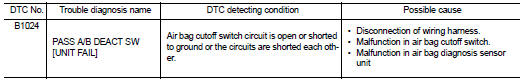
DTC DETECTION LOGIC
DTC CONFIRMATION PROCEDURE
1.CHECK SELF-DIAGNOSTIC RESULT
 With CONSULT-III
1. Turn ignition switch ON.
2. Perform ÔÇťSelf Diagnostic ResultÔÇŁ mode of ÔÇťAIR BAGÔÇŁ using CONSULT-III.
 Without CONSULT-III
1. Turn ignition switch ON.
2. Check the air bag warning lamp status. Refer to SRC-12, "On Board Diagnosis Function".
NOTE
:
SRS does not enter diagnosis mode if no malfunction is detected in user mode.
Is malfunctioning part detected? YES >> Refer to SRC-34, "Diagnosis Procedure".
NO >> INSPECTION END
Diagnosis Procedure
WARNING:
ÔÇó Before servicing, turn ignition switch OFF, disconnect both battery terminals
and wait at least 3 minutes.
(To discharge backup capacitor.) ÔÇó Never use unspecified tester or other measuring device.
1.CHECK HARNESS CONNECTOR
Check the connection of harness connector.
Is the connection normal? YES >> GO TO 2.
NO >> Replace harness connector.
2.CHECK WIRING HARNESS
Check the wiring harness externals.
Are the harness external parts normal (no damage)? YES >> GO TO 3.
NO >> Replace wiring harness.
3.CHECK AIR BAG CUTOFF SWITCH
1. Replace air bag cutoff switch..
2. Perform DTC confirmation procedure. Refer to SRC-34, "DTC Logic".
Is DTC detected? YES >> GO TO 4.
NO >> INSPECTION END
4.REPLACE AIR BAG DIAGNOSIS SENSOR UNIT
1. Replace air bag diagnosis sensor unit. Refer to SR-30, "Removal and Installation".
2. Perform DTC confirmation procedure. Refer to SRC-34, "DTC Logic".
Is DTC detected?
YES >> GO TO 1.
NO >> INSPECTION END
 B1023 passenger air bag off indicator
DTC Logic
DTC DETECTION LOGIC
DTC CONFIRMATION PROCEDURE
1.CHECK SELF-DIAG RESULT
With CONSULT-III
1. Turn ignition switch ON.
2. Perform ÔÇťSelf Diagnostic ResultÔÇŁ mode of ÔÇťAIR BAGÔÇŁ usi ...
 B1026, B1027, B1028, B1029, B1030, B1031 diagnosis sensor unit
DTC Logic
DTC DETECTION LOGIC
DTC CONFIRMATION PROCEDURE
1.CHECK SELF-DIAG RESULT
With CONSULT-III
1. Turn ignition switch ON.
2. Perform ÔÇťSelf Diagnostic ResultÔÇŁ mode of ÔÇťAIR BAGÔÇŁ usi ...
Other materials:
Cylinder block
Exploded View
1. Cylinder block
2. Top ring
3. Second ring
4. Oil ring
5. Piston
6. Piston pin
7. Snap ring
8. Connecting rod
9. Connecting rod bearing (upper)
10. Connecting rod bearing (lower)
11. Crankshaft key
12. Connecting rod cap
13. Connecting rod cap bolt
14. Main ...
C1143 steering angle sensor
DTC Logic
DTC DETECTION LOGIC
DTC CONFIRMATION PROCEDURE
1.PRECONDITIONING
If ÔÇťDTC CONFIRMATION PROCEDUREÔÇŁ has been previously conducted, always turn
ignition switch OFF and
wait at least 10 seconds before conducting the next test.
>> GO TO 2.
2.CHECK DTC DETECTION
With CON ...
Precaution
Precaution for Supplemental Restraint System (SRS) "AIR BAG" and "SEAT
BELT
PRE-TENSIONER"
The Supplemental Restraint System such as ÔÇťAIR BAGÔÇŁ and ÔÇťSEAT BELT PRE-TENSIONERÔÇŁ,
used along
with a front seat belt, helps to reduce the risk or severity of injury to the
...
