Nissan Juke Service and Repair Manual : Air breather hose
MR16DDT : Exploded View
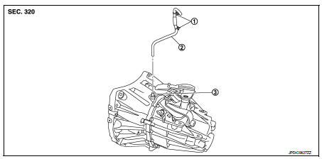
1. Clip
2. Air breather hose
3. 2 way connector
MR16DDT : Removal and Installation
REMOVAL
1. Remove air cleaner case. Refer to EM-26, "Removal and Installation".
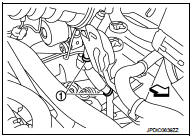
2. Remove clips (1).
 : Vehicle front
3. Remove air breather hose from the 2 way connector.
CAUTION:
When removing air breather hose, be sure to hold 2 way
connector securely.
INSTALLATION
Note the following, and install in the reverse order of removal.
CAUTION:
• Install air breather hose, preventing crush and clogging caused by bending.
• Insert the allowance of air breather hose to the spool of the 2 way connector.
• Install air breather hose to the 2 way connector with the paint mark faced forward of the vehicle.
• Securely engage the clips in the mounting hole.
K9K : Exploded View
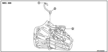
1. Clip
2. Air breather hose
3. 2 way connector
K9K : Removal and Installation
REMOVAL
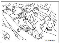
1. Remove clips (1).
 : Vehicle front
2. Remove air breather hose from the 2 way connector.
CAUTION:
When removing air breather hose, be sure to hold 2 way
connector securely.
INSTALLATION
Note the following, and install in the reverse order of removal.
CAUTION:
• Install air breather hose, preventing crush and clogging caused by bending.
• Insert the allowance of air breather hose to the spool of the 2 way connector.
• Install air breather hose to the 2 way connector with the paint mark faced forward of the vehicle.
• Securely engage the clips in the mounting hole.
 Control linkage
Exploded View
1. Bracket
2. Shifter cable
3. Selector lever
4. Shifter lever A
5. Tapping bolt
6. Cable mounting bracket
7. Selector cable
8. Grommet
9. M/T shift selector assembly
1 ...
 Unit removal and installation
Transaxle assembly
MR16DDT : Exploded View
1. Transaxle assembly
: Refer to "INSTALLATION" in
TM-84, "MR16DDT : Removal and Installation" for the locations and tightening
...
Other materials:
U0141 lost communication (BCM A)
Description
CAN (Controller Area Network) is a serial communication line for real-time
application. It is an on-vehicle multiplex
communication line with high data communication speed and excellent malfunction
detection ability.
Many electronic control units are equipped onto a vehicle, and ...
Component parts
Component Parts Location
1. Combination meter
2. Key switch
3. BCM
Refer to BCS-96, "BODY CONTROL
SYSTEM : Component Parts Location"
4. Power window main switch
(door lock/unlock switch)
5. Front door switch (driver side)
6. Front door lock assembly (driver
side)
7. Back do ...
Front door
Exploded View
1. Front door panel
2. Grommet
3. Door hinge (upper)
4. Door hinge (lower)
5. Door check link
6. Bumper rubber
7. Door pad
8. Door striker
9. TORX bolt
10. Grommet
: Do not reuse
: N·m (kg-m, in-lb)
: N·m (kg-m, ft-lb)
: Body grease
Door assembly
DOOR ASSEMBLY ...
