Nissan Juke Service and Repair Manual : Engine control system
Engine control system : System Diagram

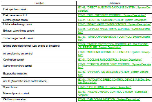
Engine control system : System Description
ECM controls the engine by various functions.
 System
...
 Direct injection gasoline system
Direct injection gasoline system : System Diagram
Direct injection gasoline system : System Description
INPUT/OUTPUT SIGNAL CHART
*1: This sensor is not used to control the engine system under ...
Other materials:
Diagnosis system (BCM) (with intelligent key system)
Common item
COMMON ITEM : CONSULT-III Function (BCM - COMMON ITEM)
APPLICATION ITEM
CONSULT-III performs the following functions via CAN communication with BCM.
SYSTEM APPLICATION
BCM can perform the following functions for each system.
NOTE:
It can perform the diagnosis modes except the fo ...
Diagnosis and repair workflow
Work Flow
OVERALL SEQUENCE
DETAILED FLOW
1.INTERVIEW FOR MALFUNCTION
Interview the symptom to the customer.
>> GO TO 2.
2.SYMPTOM CHECK
Check the symptom from the customer's information.
>> GO TO 3.
3.BASIC INSPECTION
Check the operation of each part. Check that any s ...
Draining
1. Run the vehicle to warm up the transfer unit sufficiently.
2. Stop the engine and remove the drain plug (1) and gascket to
drain the transfer oil.
3. Before installing drain plug, set a new gasket. Install drain plug
on the transfer and tighten to the specified torque. Refer to DLN-
113, &qu ...
